Designing with road strings is very similar to designing with cross-sections:
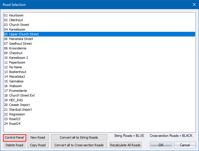
Select the road file from the project library, or click on the centreline of an existing road.
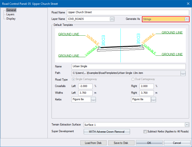
Set up the basic road parameters using the Road Control Panel.
Be sure to specify that the road must be designed using strings.
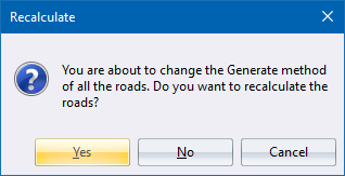
Once you close the Road Selection window, or the Road Control Panel, you are asked if you want to recalculate the road. Click Yes to convert the active road into road strings.
The strings are named according to a specific hierarchy.
When you open an existing roads project in Civil Designer, all the existing roads designed using the cross-section method continue to work exactly as before. There are three ways to change a cross section road design to a strings road design, and visa-versa.
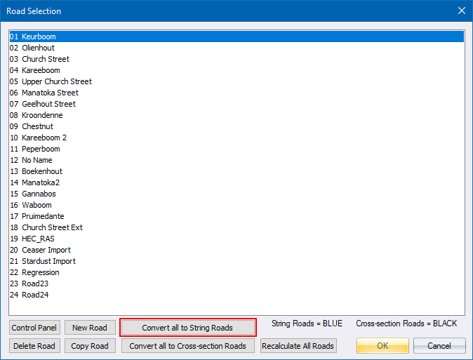
Select the Select Road File option in the File menu.
The following Confirmation message displays.
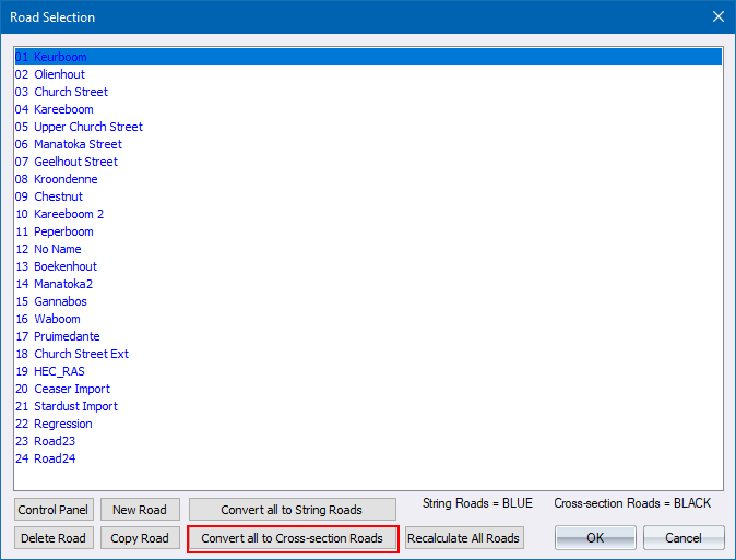
Click Yes to have all the existing roads changed to the string roads method. This may take a little while depending on the length of the road, and the chainage interval. Strings Roads are listed in blue, while cross-section roads are listed in black.
You can also use Convert all to Cross Section Roads to change all the roads back to cross-sections.
 If you change strings roads with intersections, mini-roundabouts or cul-de-sacs back to cross-section roads, the junctions are all removed.
In the Roads Control Panel, change the Generate As option.
The following Confirmation window displays.
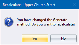
Click Yes to change the selected road to the string roads method.
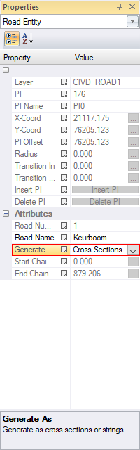
Select the road you want to change by clicking on it's centreline.
Select the Road Control Panel option in the Tools menu.

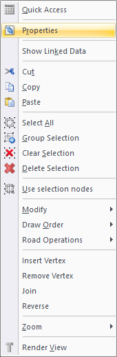
In the Properties Bar, change the Generate As property.
When designing roads using strings, the program always attempts to finish the calculations without any user intervention, from coordinating the horizontal alignment through to the Apply Template stage if the Interactive Wizard is enabled.
If the Interactive Wizard is not enabled, you have to manually coordinate the horizontal alignment, extract cross-sections, generate vertical alignment levels, generate edge levels and apply the template.
To enable or disable the Interactive Wizard, select the Option Settings checkbox and select the Roads page.
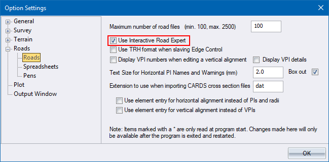
If the Interactive Road Expert has been enabled in the Option settings, Civil Designer tries to run all the calculations up to and including Apply Template.
If the Interactive Road Expert is disabled, only the operation that has been initiated via the menus is executed, as per the normal cross-section method. The Roads Expert executes the road strings functions, as per the normal cross-section method.
Re-coordinate horizontal alignment (SEC File).
Re-calculate the master string from the horizontal alignment.
Re-calculate the vertical alignments (pivot strings).
Delete all the children of the pivot strings.
Offset the pivot strings and height the strings.
Re-calculate the vertical alignments (pivot strings).
Delete all the children of the pivot strings.
Offset the pivot strings and height the strings.
From the pivot strings, generate shoulder and median strings.
Calculate the intersections and merge intersection shoulder strings.
Merge roundabout main road strings (3-way roundabouts).
Add the kerbs.
Recalculate the intersecting roads.
Calculate islands for intersections.
Recalculate the main road if this road forms part of a roundabout.
Calculate main road islands for roundabouts.
Calculate the median strings if a dual CW road.
Delete all children of the shoulder strings.
For each vertex of the shoulder strings:
Extract a temp cross-section from the ground DTM.
Run the normal Prick calculations onto a temp batter cross-section and generate the strings from these cross-sections.
Set the toe-calculate settings and recalculate the string so that the toe points can be calculated.
Smooth toe points for variable slope batters.
Update the display settings.
Extract design sections from strings.
The Road Recalculate function is designed to give you a quick way of performing a pre-defined set of calculations. The calculations that are performed are specified in Road Recalculate Settings.
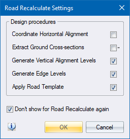
If you have the function set up like this, the program re-generates the edge levels and applies the road template every time you run the function.
A junction can be an Intersection, a Mini-roundabout or a Cul-de-sac. You can design a junction using the Add functions in the Junction menu.
After you have designed a junction, you can edit it by selecting the Edit Junction option in the Junction menu. Thereafter, you identify the junction to be changed by clicking on the intersecting road near the junction you want to edit.
You can also delete a junction by selecting the Delete Junction option and clicking on the intersecting road near the junction you want to delete.
For an explanation of how Civil Designer calculates quantities for roads with junctions, refer to the Junctions help topic.
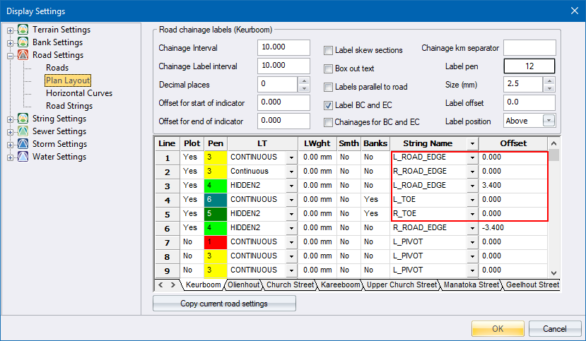
For roads designed using the cross-section method, you can control how the road is displayed by specifying cross-section layers and PLC codes, or fixed offset values in the Plan Layout page in the Display Settings.
For roads designed using the strings method, you have to specify which strings to display. Each road feature is defined by a string, which is listed in the String Name column of the Plan Layout page. Refer to the string hierarchy for more about string names.
Below is a brief description of what the string names mean.
|
String Name
|
Description |
|
CENTRE LINE |
Road Centre line |
|
ROAD_EDGE |
Road edges or edge of carriageway (PLC 100 and -100) |
|
SHOULDER_BP |
Last compulsory point |
|
SHOULDER_Krb and MEDIAN_Krb |
The back of kerb strings on the shoulder and median respectively |
|
SHOULDER_Krb# |
These strings define the other kerb points between the road edge and back of kerb string |
|
MEDIAN_Krb# |
These strings define the other kerb points between the median edge and back of kerb string |
|
COMP_# |
The other compulsory points from the back of kerb string to the SHOULDER_BP string |
|
BANK |
The top of bank point (PLC 98) |
|
BANK_# |
These strings define the other cut/fill points created by the templates (drains or berms) |
|
TOE |
The toe string |
You can also draw a line at a specified offset from any string, by specifying the reference string and using the Offset column to specify the offset.
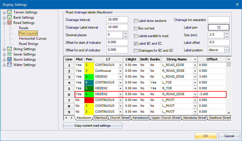
In the example above you are adding a line 1.0m to the left of the centre line.
In addition to these lines, you can also opt to display the road as shaded. Simply check the Display shading option as shown below.
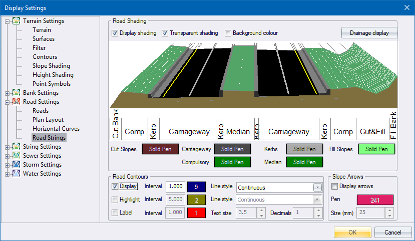
If you want to view a 3D rendered image of the road, you have to switch on the Display Shading option.
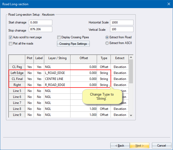
Plotting using road strings is very similar to using cross-sections, with some extra options.
When plotting road long sections of roads designed as strings, you can still refer to the cross section offsets and PLC codes in exactly the same manner as before.

But, you also have the option to plot the long section by specifying which strings to plot. Change the values in the Type column to “String” and specify the string you want to plot in the Layer/String column.