You can right-click on the row header to Insert an additional line into the display list.
Option
|
Description |
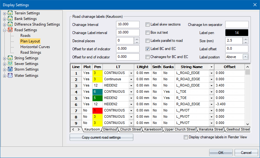
Road chainage labels |
|
Chainage |
Enter the interval between successive chainage indicators. |
Chainage Label Interval |
Enter the interval between successive chainage labels |
Decimal places |
Enter the number of decimals to be displayed in the chainage labels. |
Offset for start of indicator |
Enter the offset from the centreline at which the indicator line should start drawing. Offsets to the left of the centreline should be entered as a negative value. |
Offset for end of indicator |
Enter the offset from the centreline at which the indicator line should stop drawing. Offsets to the left of the centreline should be entered as a negative value. |
Label Skew Sections |
Select this checkbox to label all the skew sections with the change label and skew angle. If this checkbox is selected, skew sections will always be labelled regardless of the Chainage Interval. |
Box out text |
Select this checkbox to box out the label text. |
Labels parallel to road |
Select this checkbox to have the labels placed parallel to the centreline, instead of at right-angles. |
Label BCC and ECC |
Select this checkbox to have the beginning and ending of curves labelled, in addition to the regular chainages. |
Chainages for BC and EC |
Select this checkbox to display the chainages for the BCC, ECC BTC and ETC points. |
Chainage km separator |
Enter the kilometre separator. If you enter "km" chainage 1250 will be written as "1km 250" on the road plan. |
Label pen Button |
Click this button to select the colour in which to display the labels. |
Size (mm) |
Enter the size of the labels in mm. |
Label offset |
Enter the offset from the centreline where the labels should be plotted. |
Label position |
Enter the position of the chainage label relative to the chainage coordinate on the centreline. This option can be set to Above, Below, Left or Right. |
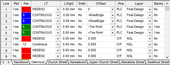
Data Table |
|
Plot column |
Select whether the particular line should be plotted or not. Enter either Yes or No in the cell, or right-click the cell to toggle the current setting. |
Pen column |
Enter a pen number or right-click the cell to display the colour options in order to specify a pen with which to plot the line. |
LT column |
Enter the number of the line type in which to display the line. |
LWght column |
Specify the line width for this line. |
Smth column |
Select whether the line should be smoothed or not. Enter either Yes or No in the cell, or right-click the cell to toggle the current setting. |
Offset column |
Enter either the offset or ID or select the point location code (PLC) of the cross-section point that should be used for plotting this line.
|
Pos column |
Specify whether the entered value in the Offset column is a point location code, point ID or an offset. Right-click the cell to alter the current setting. |
Layer column |
Right-click the cell and select the layer from which the cross-section data should be extracted. |
Banks column |
Change this to Yes to display bank lines from this line to the previous line working towards the centreline of the road. This allows you to display multiple sets of bank lines. |
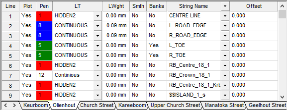
Data Table |
|
Plot column |
Select whether the particular line should be plotted or not. Enter either Yes or No in the cell,or right-click the cell to toggle the current setting. |
Pen column |
Enter a pen number, or right-click the cell to display the colour dialog so you can specify a pen with which to plot the line. |
LT column |
Enter the number of the linetype in which to display the line. |
LWght column |
Specify the line width for this line. |
Smth column |
Select whether the line should be smoothed or not. Enter either Yes or No in the cell, or right-click the cell to toggle the current setting. |
Banks column |
Change this to Yes to display bank lines from this line to the previous line working towards the centreline of the road. This allows you to display multiple sets of bank lines. |
String Name column |
Select the string name that should be displayed.
|
Offset column |
Specify the left (-) or right (+) offset from the specified string in the String Name column. |
Change all roads to these settings |
Click to copy the visible settings to all the existing roads. |
Display chainage labels in Render View |
Select this checkbox if you want to draw your chainage labels in Render View (defaults to OFF). This option only impacts the way you draw the roads in Render View. |