 The junction functions
are only applicable if all the roads have been designed using the strings
method.
The junction functions
are only applicable if all the roads have been designed using the strings
method.Home > Roads Mode > Junctions
A junction is a junction, mini-circle, roundabout or cul-de-sac.
Each road can have only two junctions, one at the start of the road and one at the end of the road. In essence, the junction is associated with the intersecting or incoming road and not the through road.
The junction functions
are only applicable if all the roads have been designed using the strings
method.
The junctions are part of the intersecting road. Each road can have a junction at its start and at its end. The junction design is done using the following convention:
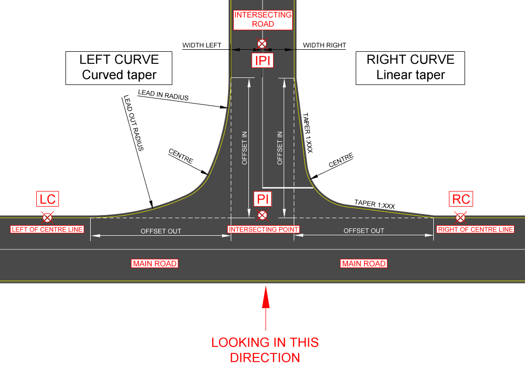
Label
|
Description |
LC |
Main road left of junction. |
RC |
Main road right of junction. |
PI |
Intersecting point on main road. |
IP1 |
Intersecting road. |
Horizontal coordinates are generated exactly along the geometry specified.
During the recalculation of the edge levels the following procedure is followed:
The junction between the PIVOT strings of the two roads is calculated.
The junction edge string runs from the main (through) road edge, along the lead in taper/curve, the junction edge curve and finally along the lead out taper/curve, to tie in to the intersecting road's edge.
The bell mouth is filleted between the main and intersecting road edges in 2D using the specified curve radius.
The grades of the main and intersecting road edges are calculated at the point where the junction bell mouth starts.
The bell mouths are graded using one of two methods, depending on the S-Curve setting made in the Junction Layout.
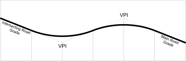
Vertical coordinates (elevations) are generated by means of two vertical curves. First, the overall distance is divided into six parts. The first sixth and the last sixth are straights that conform to the grades of the intersecting road edges. In the remaining space, two equal and butting vertical curves are fitted. Therefore, the two VPIs are at one third and two thirds of the way along the overall coordinated stretch, as shown above.
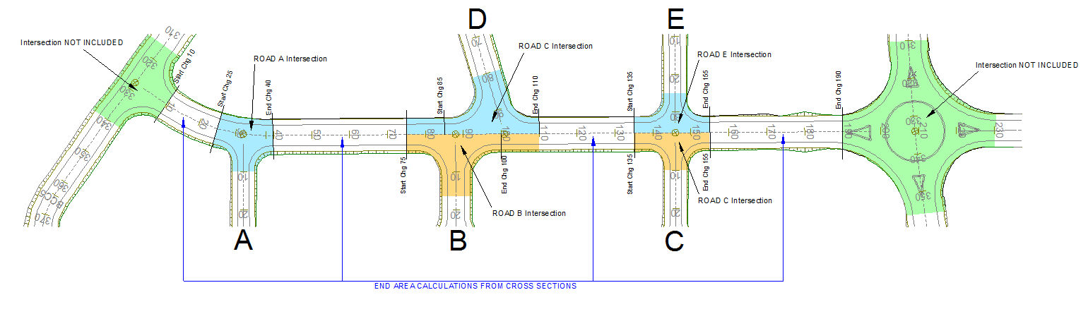
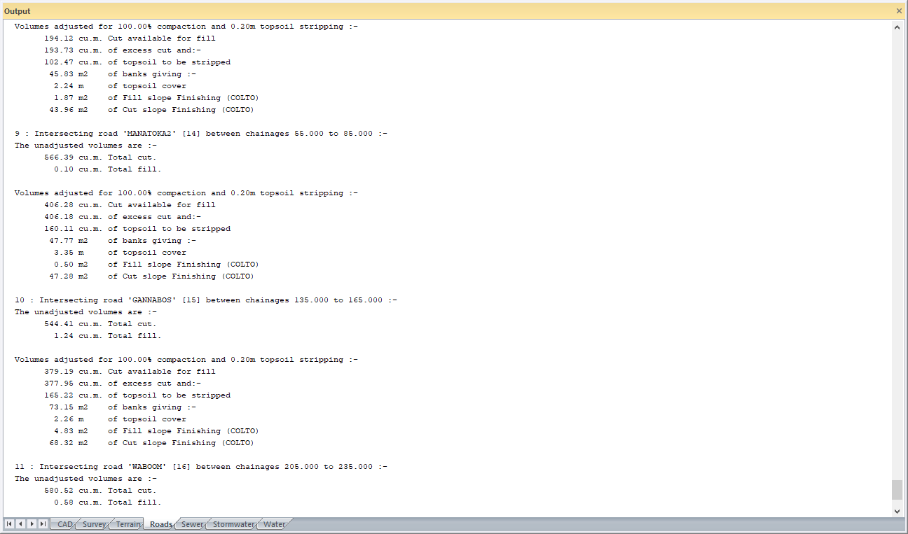
Masshaul/Cumulative Volumes, Road Footprint Area and Layerwork volumes calculations are done using the end-area method from the cross-sections (as per the cross-section method) for the current road, for portions of the road where there are no incoming junctions. The portions of the current road where there are incoming junctions are omitted from the end area calculations.
Each junction that intersects the current road is calculated using prisms, and is listed separately (blue fill). The current road’s intersections at the start or end of the current road are not included. They are included with the road into which they intersect (green fill). When there are junctions on both sides of the current road, and they overlap each other, the quantities are calculated up to the current road’s centre line (see drawing below – blue and orange fill).
The Plan section of the sheetfiles now contain two extra sections:
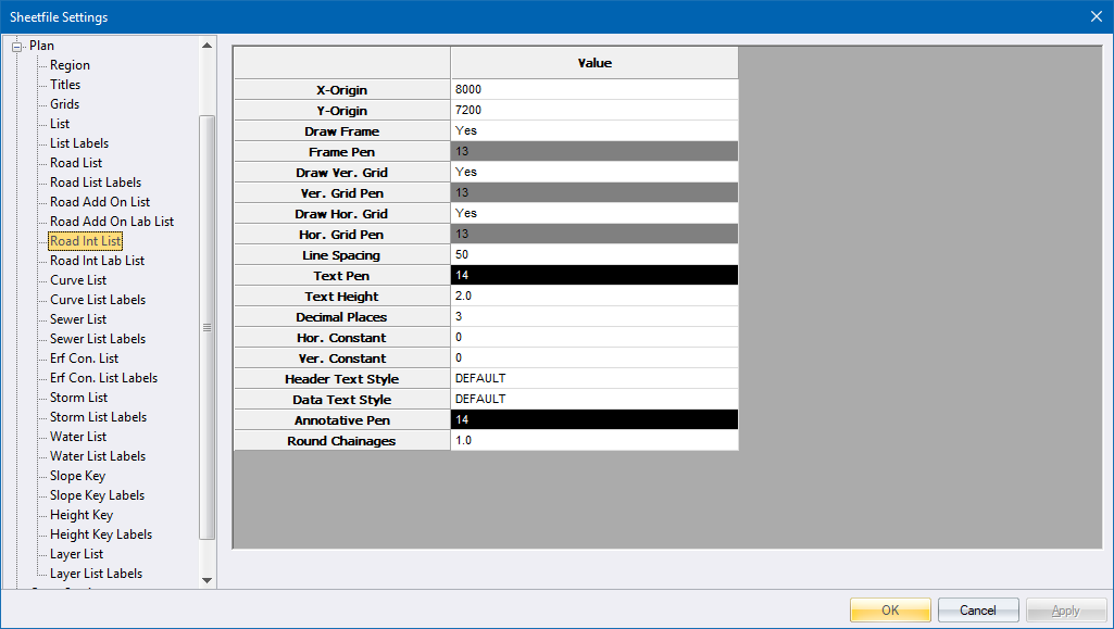
The Road Int List specifies the plotting parameters of the junction coordinate table layout.
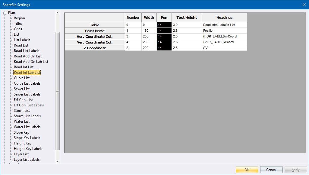
The Road Int Lab List specifies the junction coordinate labels.
Note the use of
the Annotation Pen and Round Chainage items in the Road Int List section.
Item
|
Description |
Annotation Pen |
The point names are written on the bell-mouths in this colour. The text height can be set in Display Settings, Terrain page (same as the DTM point names). The point names and coordinates are tabulated using the settings on this page and the previous page. |
Round Chainage |
The Start, End, BC, EC and Centre points are always listed. For junctions and roundabout bell-mouths, if you specify a value other than Zero (say 1m), a point is listed every 1m, provided that the coordination interval used to generate the junctions is a factor of this value. Cul-de-sac only lists the BC, EC and centre points. |
To plot a junction, use the Plan.sht sheetfile and generate a plot at a suitable scale.