Snap on first plane point
Snap to the first point that defines the interpolation plane.
Snap on next plane point
Snap on the second point that defines the interpolation plane.
Snap on next plane point
Snap on the third point that defines the interpolation plane.
Indicate position for new point
Click on the position of the new point.
Add a roundabout.
Icon |
Command |
Shortcut Key |
Toolbar |
|
RD_CALCSTOCKDALEROUNDABOUT |
|
|
This function allows you to add a roundabout using the Stockdale method.
A roundabout has the following properties:
May have more than four incoming legs.
Can be non-circular.
Each leg of the roundabout must be a separate road.
The roundabout circle is also be created as a separate road.
The Stockdale Method is used for vertical design.
Drawing entities are used to define the entry/exit lanes.
Kerb lines can have any shape.
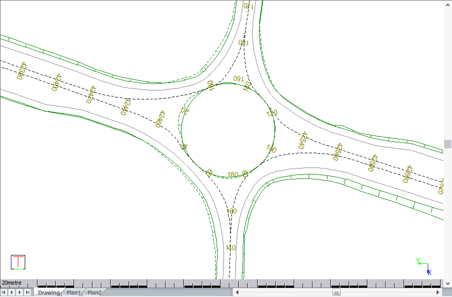
The horizontal layout of the roundabout should be drawn in CAD as shown below.
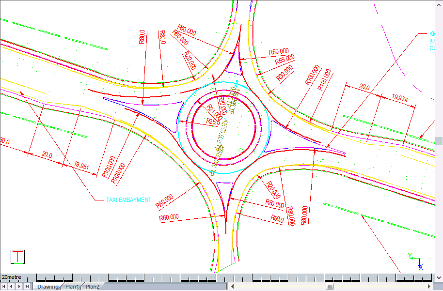
Design separate approach roads for the roundabout as string roads. These roads have to be dual carriageways, and you must simulate a single carriageway as a dual carriageway with the CL to Pivot distance and the Pivot to Median distance in the Edge Control equaling zero. The configuration of the approach roads should look like this:
Draw the crown lines of the roundabout in CAD (plan only, no Z-coordinates needed). Crown lines are imaginary lines that usually indicate a change in the degree of crossfall across a road, and are the lines that surfacing equipment works to during construction.
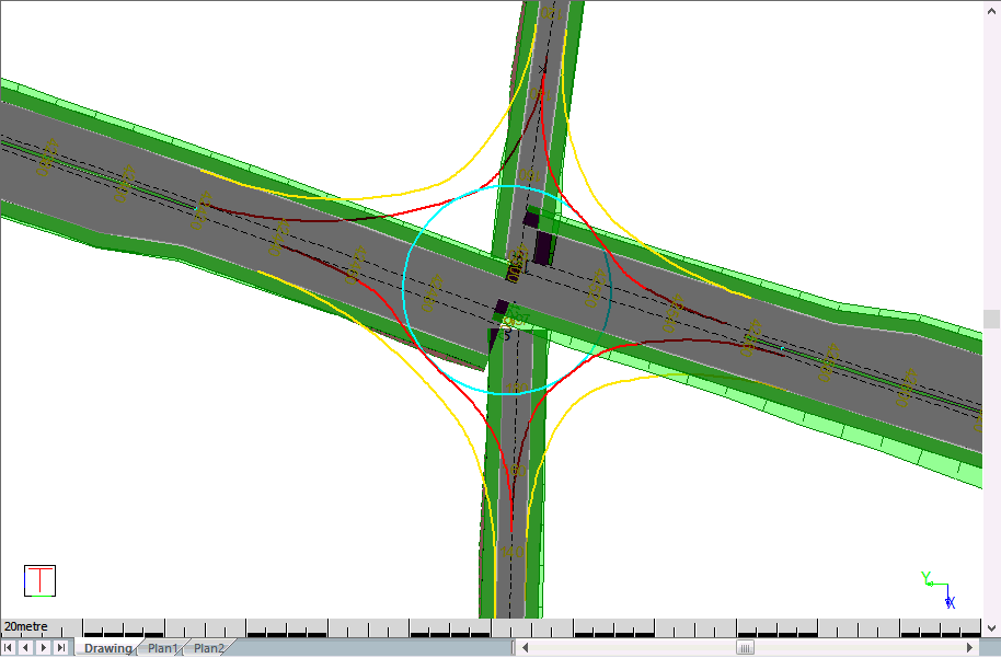
You could also draw the road edges within the roundabout as follows (thick yellow lines). This is optional. If you do not indicate the edge lines when designing the roundabout, it simply uses the Edge Control widths (Pivot to Shoulder values).
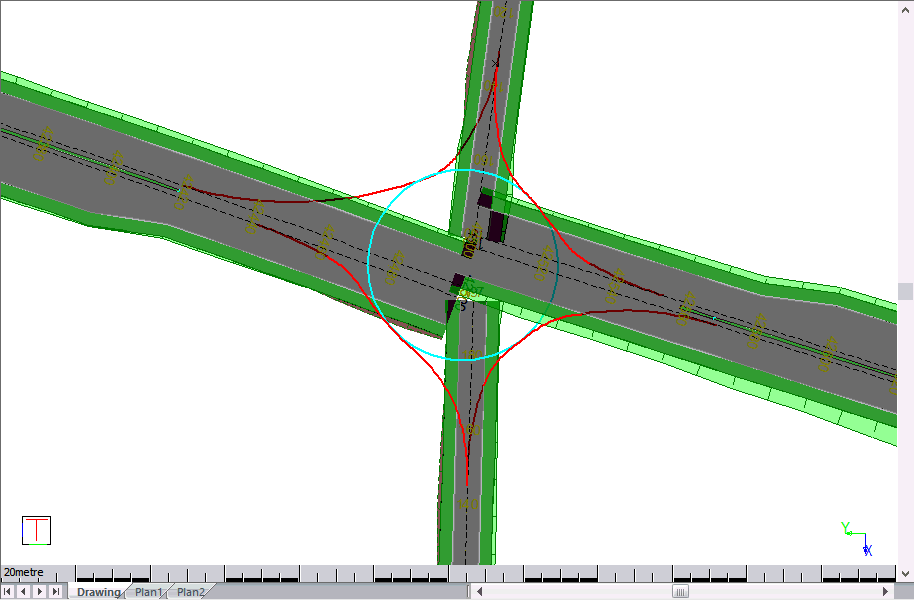
In this example, the “roundabout crown” is drawn in cyan and the “Entry / exit crowns” are drawn in red. The road edges inside the roundabout are drawn in yellow. These lines can be drawn using any entity (arcs, circles, lines or polylines). They can also be any combination of entities and do not have to consist of a single entity.
Civil Designer automatically creates a new single carriageway road entity for the roundabout. You can control the width of the roundabout and crossfalls using the Edge Control.
The approach road left and right pivot strings ( L_PIVOT and R_PIVOT are adjusted and heighted using the Stockdale method to follow the red lines on the drawing above.
The crossfall specified in the Edge Control of the approach roads is applied. If you did not specify edges, the last/first “pivot to shoulder” value is used.
The width and crossfall specified for the roundabout circle road is applied and the batter slopes intersect with the approach roads.
You can change the crown line heighting by selecting Edit Junction and clicking on the roundabout road. The Long Section Editor with the crown strings displays.
You can use Addon Strings to define islands. Make sure you define the islands in a counter clock-wise direction if you want to add kerbs to them.
You can delete the roundabout using the Delete Junction function and clicking on the roundabout road.
You can alter the roundabout widths and crossfalls by selecting the roundabout road, right-clicking and selecting Edge Levels from the context menu.
The roundabout road has no horizontal or vertical alignment.
If you want to display contours for the roundabout, switch transparent shading off in order to hide the contouring of the approach roads underneath the roundabout road.
Procedure
Before you add a Stockdale roundabout you need:
A roundabout layout drawn in CAD. The crown lines and edges of the roundabout must have been drawn as polylines and/or arcs.
Four approach roads designed as string roads, as shown above. Remember that single carriageway roads must be simulated as a dual carriageway with the CL to Pivot distance, as well as the Pivot to Median distance in the Edge Control, equalling zero. This is because each individual lane needs to be modified for the roundabout.
Select Junctions ► Add Roundabout in Roads mode.
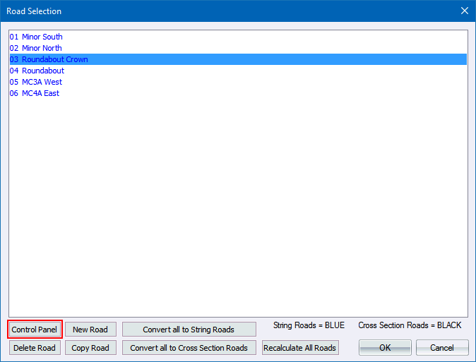
The Road Selection list displays. Select an empty road file for the roundabout crown line and click New Road.
Set up the roundabout crown name and other parameters in the Road Control Panel.
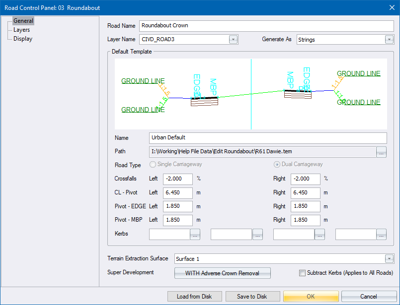
Click OK to close the Road Control Panel.
Click OK again to close the Road Selection.
You are prompted to:
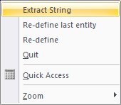
Indicate roundabout crown (right click to extract string)
Select the cyan circle, right-click and select the Extract String option from the context menu.
You are prompted to:
Indicate entry/exit crown number 1 (right click to extract string - Esc to cancel)
Select all the entities that define the first entry/exit crown line. Right-click and select the Extract String option from the context menu
You are prompted to:
Indicate the ENTRY point of the selected Crown Line
Snap to the start point of the selection set that represents the entry crown line.
You are prompted to:
Indicate the EXIT point of the selected Crown Line
Snap to the end point of the selection set that represents the exit crown line.
You are prompted to:
Indicate the road edge number 1 (right click to extract string - Esc to use road shoulder width)
Indicate the road edge of the crown line you are defining if it has been drawn. Now right-click and select the Extract String option from the context menu.
Confirm that the highlighted entry/exit crown line is correct. Click Yes to accept the existing entry; or No to redefine the crown line.

If you have accepted the crown line, you are prompted to:

Click Yes to add another entry/exit crown line; or No to proceed to the Stockdale calculations.
Define the rest of the crown lies and road edges, as above, in an anti-clockwise direction; or select No.
The program completes the Stockdale calculations as follows:
At each entry or exit crown line, a level and longitudinal slope is picked up from the underlying roads.
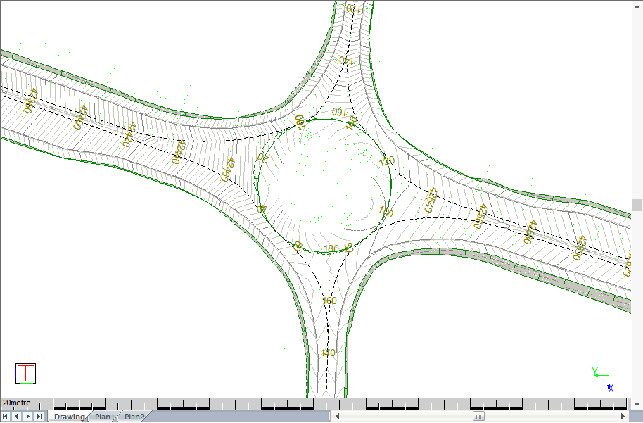
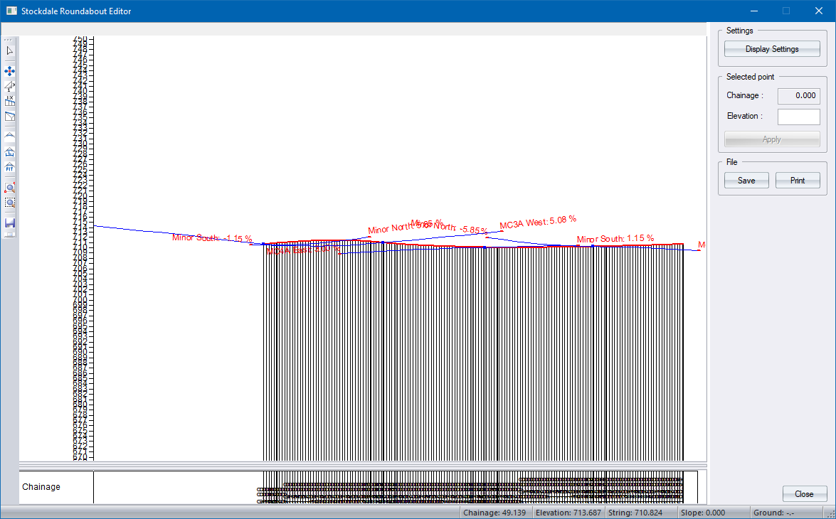
Chainages are calculated where the entry or exit crown lines touch the roundabout crown lines (kiss-points). The chainages run along the roundabout crown line. The incoming roads grade line are all drawn on the same chainage system in blue, as shown below.
Each entry and exit crown line is then heighted using an s-curve, similar to the s-curves used for intersection bellmouth design.
Lastly, the roundabout crown line is heighted using a cubic spline that runs through the kiss-points, shown in red below.
The results display in the String Longsection Editor.
Use the mouse wheel to zoom in/out.
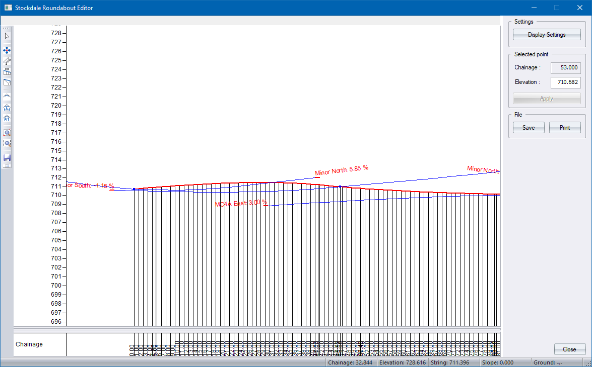
You can change the colours of the crown lines using the Display Settings.
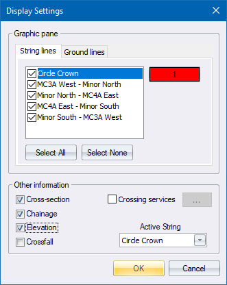
You can display the cross-section at the cursor position.
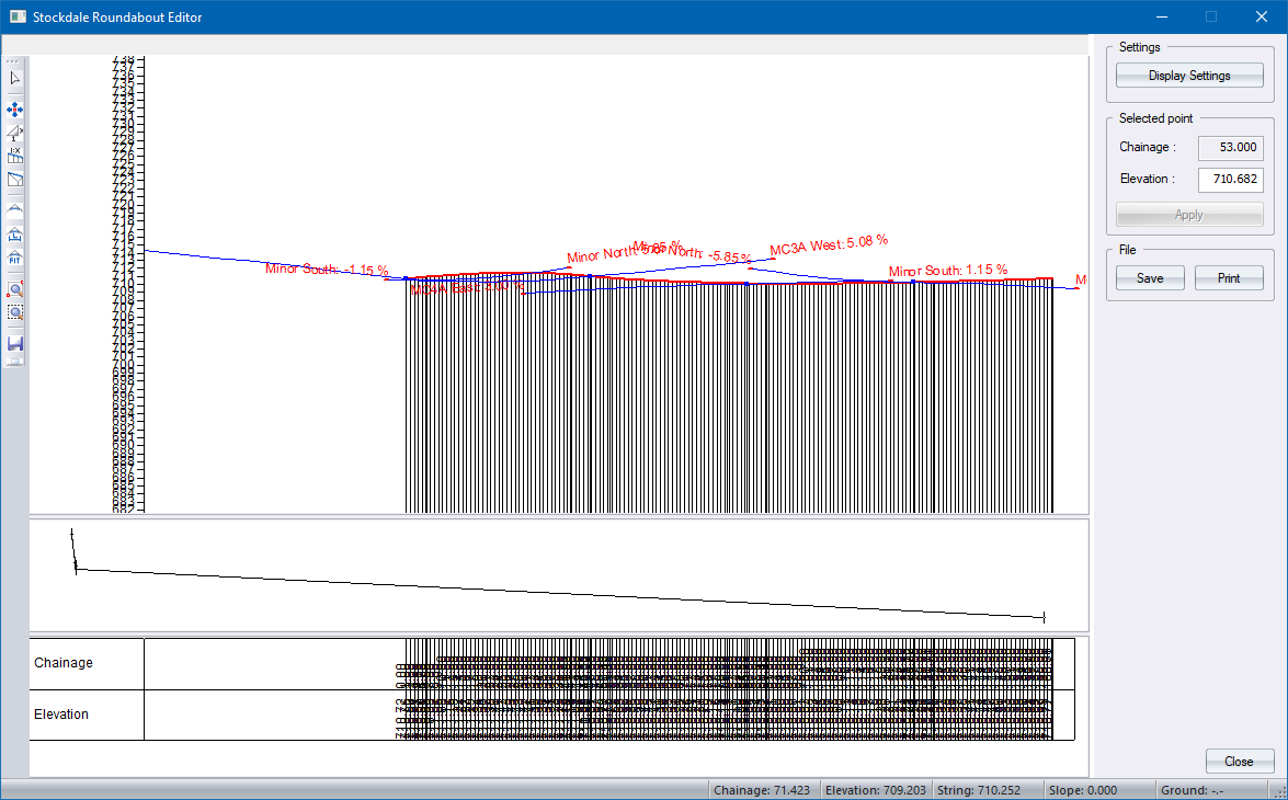
You can edit the crown line strings using the normal strings editing functions, such as Interpolate, Grade, and Smooth Vertical Curve. The “Active String” is the crown string that can be edited and is displayed as a thick line.
Click Close to continue.
The Roundabout Setup displays.
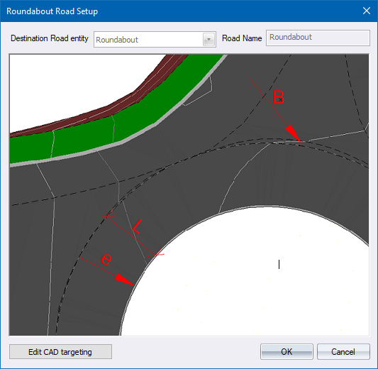
Click OK to finish the calculations and insert the roundabout into the plan.
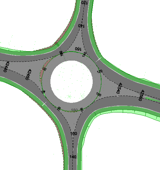
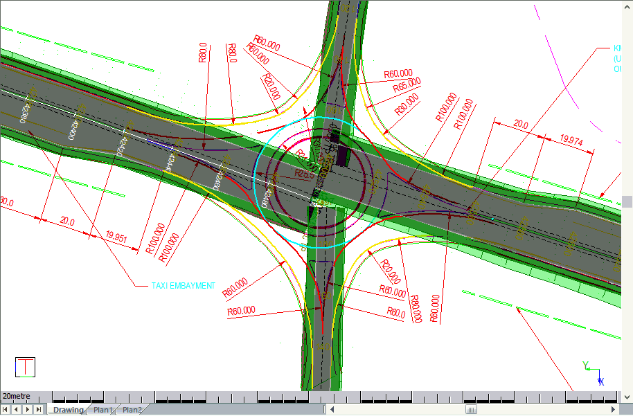
Switch on Road Shading.
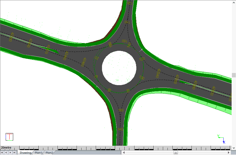
Alternatively, switch on close-spaced contours.