The template is broken down into five distinct zone types or areas:
The road profile, which contains basic carriageway details.
The median, which is an optional zone peculiar to dual carriageways.
Zones of compulsory details, which are optional. One per side.
Cut and Fill dependant zones. Both must be defined for each side.
Layerworks details. One per side.
Other than the first and last items, all the others are entered by specifying progressive offset and elevation pairs.
It is possible to create a template from scratch with a text editor, but considerable care is needed to achieve this successfully. See the section on Road Template File Components for the requirements of a template.
Templates are normally created and/or edited using the Template Editor function.
For a normal road template, the carriageway widths and percentage grades left and right are specified. This is the distance between centreline and nominal road edge. Grades are given positive for a rising slope and negative for a downward slope, when viewed from the centre.
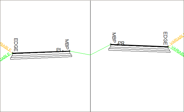
For a dual carriageway template, the distance from the centreline (CL) to the left and right pivot point must be supplied. To specify the carriageway widths, the distances from the pivot point to the Median Break Point (MBP) and to the road edge are given for each carriageway. The pivot point can be on or off the actual carriageway. Percentage grades are provided as for the normal road.
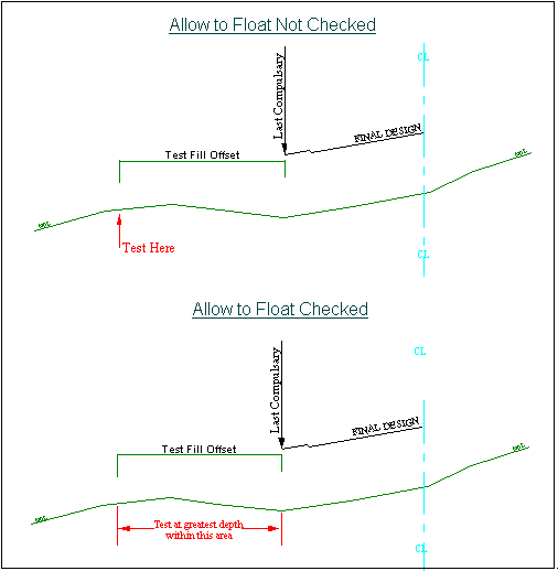
A cut/fill testing distance is required. This dictates where the ground is tested, to see if the design is in cut or fill. In other words, if 4 is entered, a test takes place when calculating the batters to see whether the ground 4m beyond the last compulsory addition is in cut or fill. Depending on the result, the appropriate cut or fill condition is applied. If 0 is entered, the test takes place at the last compulsory point.
The Allow to float option, when set for a particular template, allows the cut/fill test offsets to float out to the position of greatest difference. The normal procedure is that the depth at the specified cut/fill test offset is used to determine the correct template addition. If the Float option is specified, the depth used is the greatest depth difference found between the last compulsory point in the batter section and the points in the base section from the offset of the last compulsory point, plus or minus the cut/fill test offset to the base section extremities.
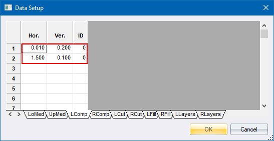
These optional offset and elevation pairs are used to define the median details of a dual carriageway template.
Two sets of pairs can be entered:
The Upper Median details are added to the higher of the two median break points in each section.
The Lower Median details are added to the lower of the two.
If the MBP heights are the same, the Lower details are added to the left MBP and the Upper details to the right MBP.
Details are added to the MBP working outwards from the carriageway, in other words, towards the centre of the section.
In the final road section, the last point from the upper median and the last point from the lower median are directly connected.
Therefore, care should be taken to ensure that the total offsets for this zone do not exceed the median width. It is normal to specify a median drain condition from the lower median, and extend it as far as the bottom of the drain. The specification from the upper median runs as far as the inner edge of the drain.
 This means that any divergence in shoulder elevations between the two carriageways is taken up in the slope leading into the drain.
These optional offset and elevation pairs are used to define road shoulder details that are added to the edge of the road profile, regardless of whether the section is in cut or fill. This is shown as the blue line in the template below.
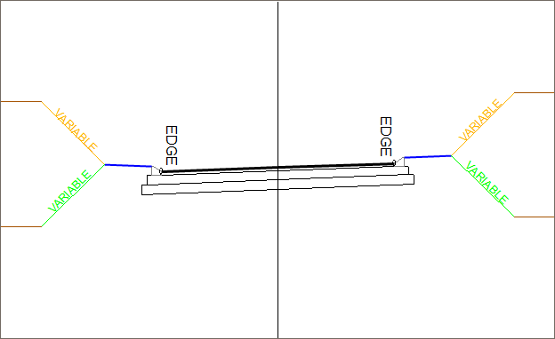
Typical uses include road shoulders, sidewalks, kerbs and channels, etc. The left and right sides are independently specified.
The last compulsory point is the point where the cut/fill profiles are applied, i.e. the shoulder break point.
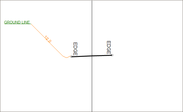
These compulsory offset and elevation pairs are used to define the cut and fill details to be applied to the left and right side of the road. They are added to the last Compulsory Detail point, or to the edge of the road profile if no compulsory details were specified. These details are usually used to define drains or benches that only occur in cut situations, and shoulders or widening for guard rails that can only occur in fill situations. The slope of the final batter to be applied is also specified.
For each situation (cut or fill, left or right) various different conditions can be set for specific depths of cut or fill. An example of a detail containing two conditions follows.
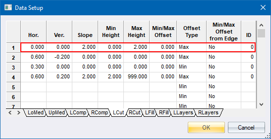
The first condition is defined by the first line only. It does not contain any offset and elevation pair details, but has a batter slope of 1:2 and is applied where the depth between the cut/fill test point and the ground is between 0m and 2m. In other words, a simple batter alone.
If the depth between the cut/fill test point and the ground is between 2m and 999m, the second condition is applied.
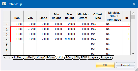
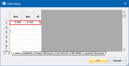
This consists of three offset and elevation pairs [(0.60, -0.20), (0.30, 0.00) and (0.60,0.20)]. These points, which represent a typical simple trapezoidal drain, are added to the section before the batter of 1:2 is applied.
Other conditions could be created by applying different height ranges. The presence of a value in the slope, min. height and max. height fields, is used to terminate a condition.
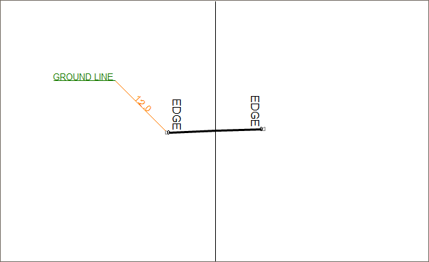
A minimum offset value can be entered. It is used to force the intersection of the batter and ground to occur at a minimum specified offset from the CL.
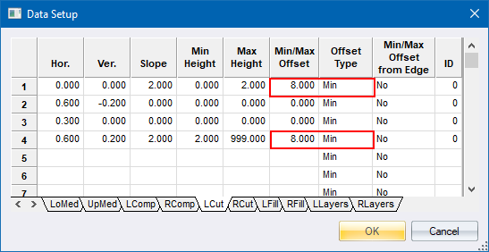
In the example above, the minimum offset has been set at 8.0m, measured from the CL.
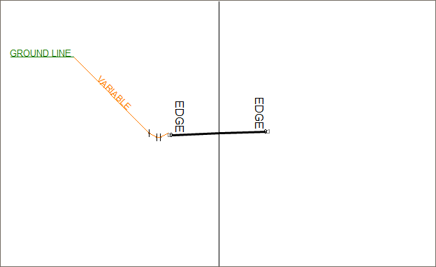
However, if the Min Offset from Edge is set to Yes, the minimum offset is measured from the edge of the carriageway. If the intersection of the batter and ground falls within this offset, the batter slope is 'flattened' until the intersection occurs exactly at the correct distance.
Details must be specified for all four possible cut or fill conditions, namely, Left Cut, Left Fill, Right Cut and Right Fill. The minimum requirement would be to enter the batter slope and a universal height range for the condition, like '0' to '999).
These are optional details which can be used to specify additional layers in the road profile. They consist of left and right PLCs at which the layers should be applied, additional optional shifts that are added to the PLCs in order to widen any particular layer, the depth of the specified layer, and a description of the layer.
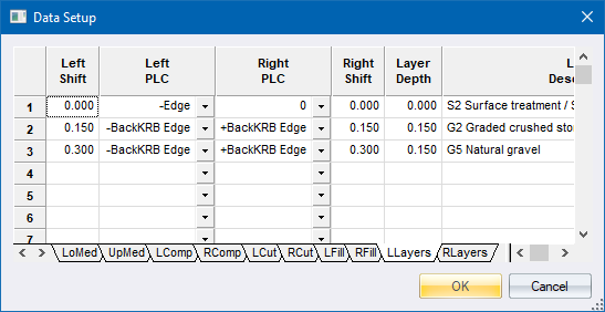
For single carriageway roads, only the left layerworks details are applied. For dual carriageway roads, both the left and right layerworks details are applied. If, however, no right layerworks details have been specified, the left layerworks details are applied across both carriageways and the median.
These layerworks details can be used to calculate simple volumes using Layerwork Volumes, or they can be used to generate extra layers in the road database using Solidify Layerworks.
The horizontal value entered is the distance from the preceding to the current point, while the vertical value entered is the difference in height from the preceding to the current point. These offset and elevation pairs are applied progressively outward from the starting point.
Note that in all cases where there is a vertical value entered, there should be a horizontal value entered as well, even if it is only 1mm. This is to ensure that no truly vertical planes are generated, which can cause problems in the Terrain and Roads functions.
There are two special elevation difference codes:
An entry of '888' produces an extension of the preceding grade, whatever that might be. It can therefore be used for such purposes as the extension of carriageway widths that have to track the road profile, whatever the state of superelevation or cross fall at that section.
An entry of '777' produces an extension of the road crossfall grade. This can be used to extend the section at the road cross fall grade even though the extension is not preceded by the carriageway section, i.e. for an additional lane at the road cross fall after a gutter channel.
A cautionary note regarding re-entrant templates:

Re-entrant designs can be specified on templates. These have particular relevance for stepped layerworks. Note, however, the comments in Sectional Areas on re-entrancy regarding the caution that should be exercised when editing these profiles manually.
Generally, it is preferable to have a separate template for each individual layer rather than a single template that encompasses several layers and thereby requires a re-entrant design. Alternatively, make use of the Layerworks function, along with the Solidify Layerworks function, in order to generate individual layers from a single template.