Template Editor
Create new road templates, or edit existing ones.
Icon |
Command |
Shortcut
Key |
Toolbar |
|
RD_TEMPLATEEDITOR |
|
|
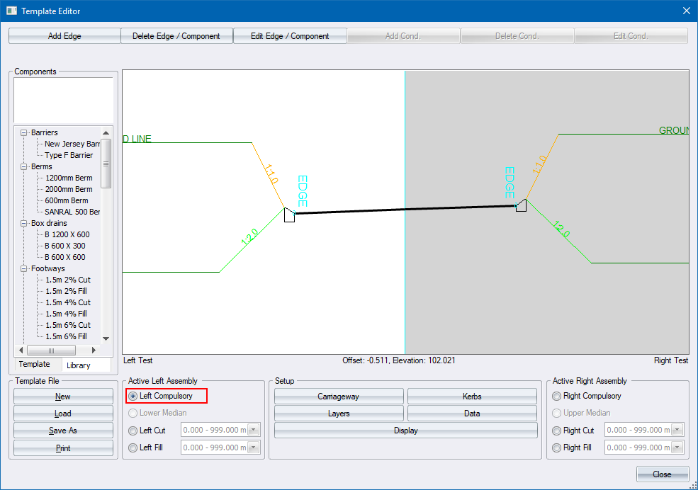
This function displays the Road Template Editor, which
allows you to apply the design or editing of templates to roads. Both
single- and dual carriageway templates can be designed.
See the Road Templates section for
more details on templates.
Procedure
- The Template
Editor displays.
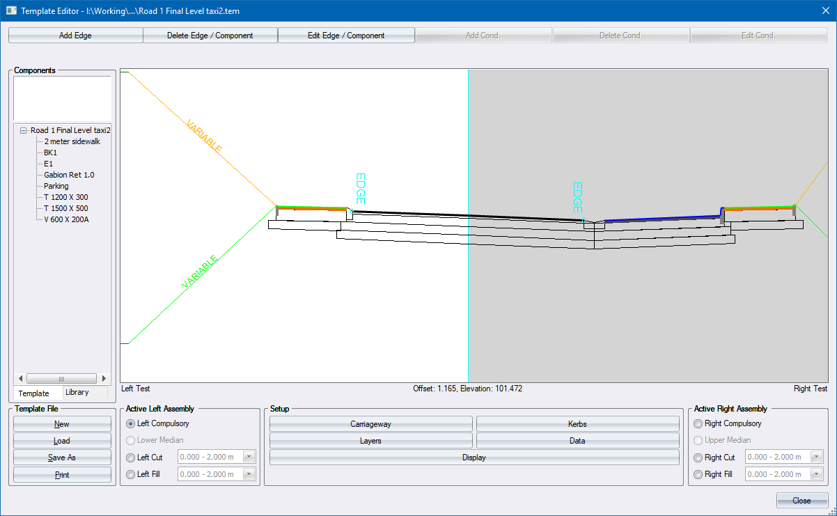
Input the required data and click
Close to exit.
To save the template, click Save As or Close.
The following massage displays.
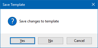
- Click Yes to specify a
template name and save the data.
Create a New Single Carriageway Template
- Open the Template Editor.
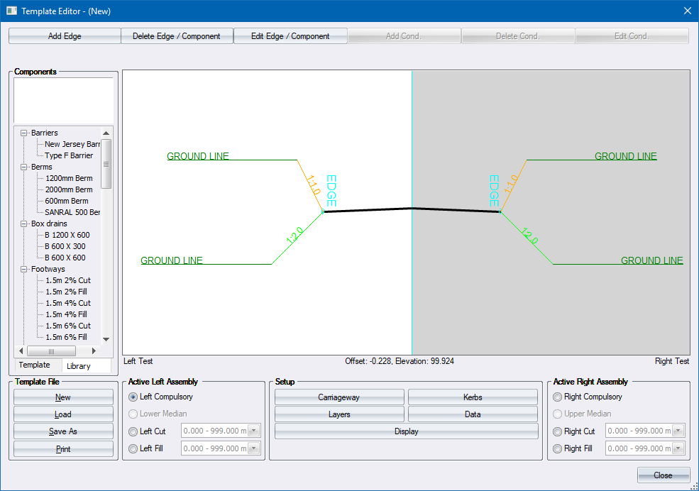
- The first step is to specify if this is a single or dual carriageway
template. Click Carriageway
to display the Carriageway
Setup.
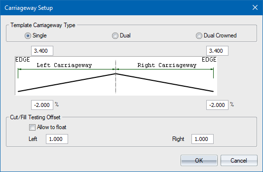
Change the carriageway widths to
3.7m left and right, and change the right crossfall to +2.0% for a
typical urban street.
Click Close
to return to the Template Editor.
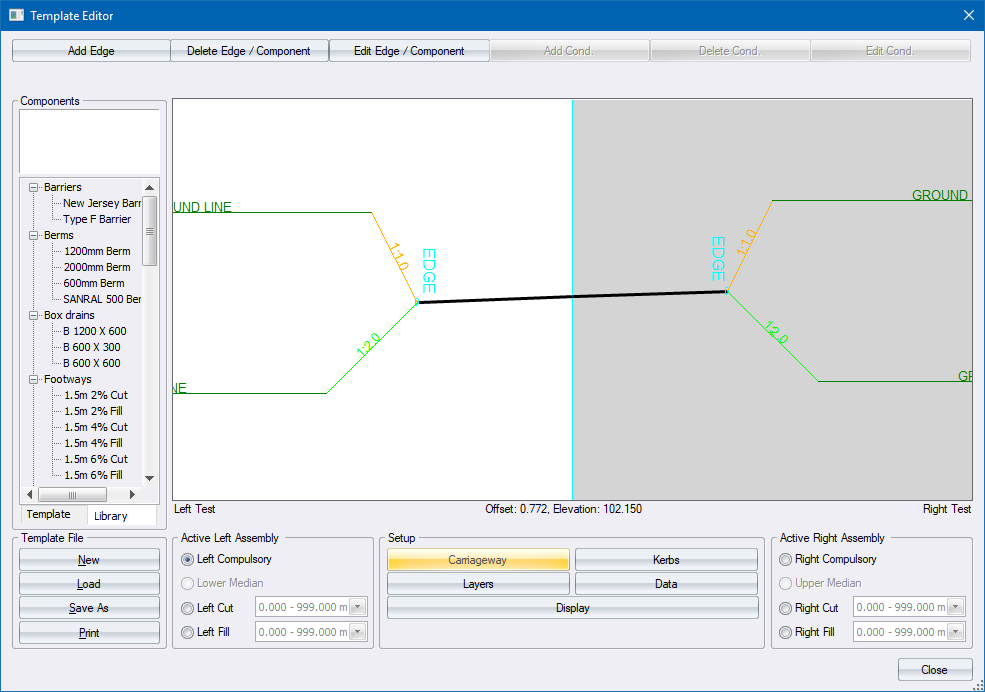
The template illustration is updated
to show the Carriageway settings.
- Now add kerbs to the road - a barrier kerb on the left edge, and
a mountable kerb on the right edge. Click Kerbs
to display the Kerb
Settings.
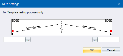
- Click the left ... to display
the Kerb
Selector.
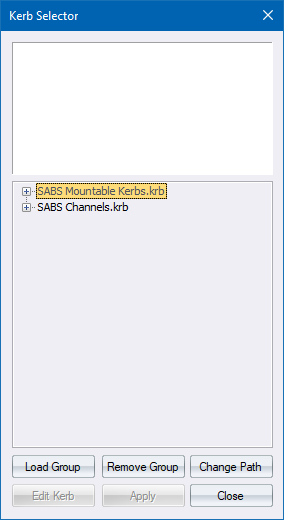
- Click Load Group to load
one or more kerb groups.
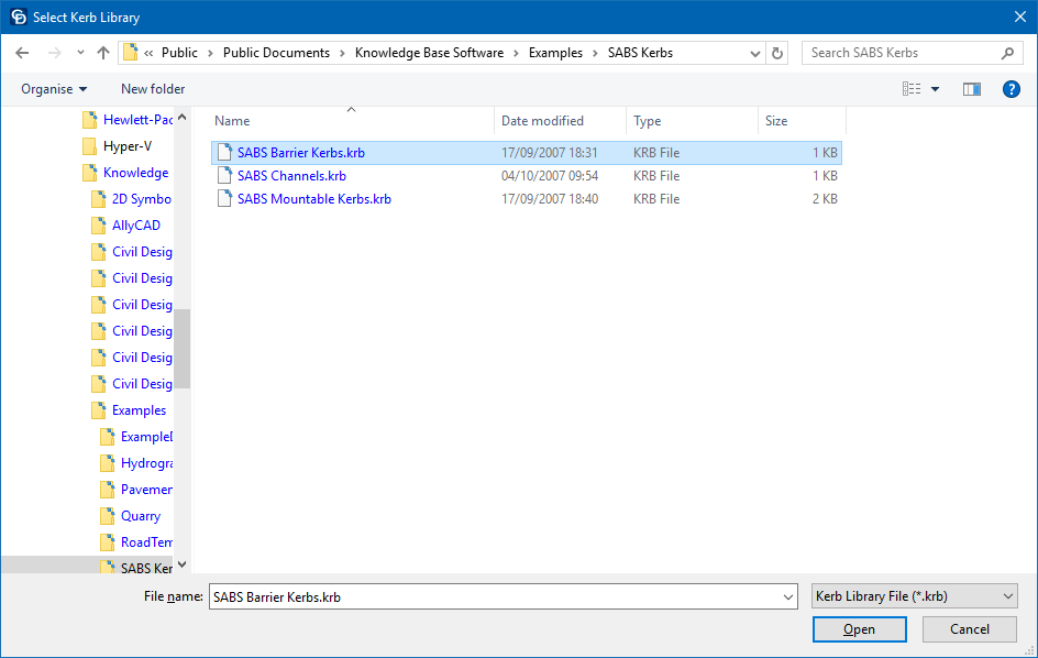
In this instance you need to load
the Barrier Kerbs. Select the item and click Open.
- The Kerb Selector is updated with the Barrier Kerb range.
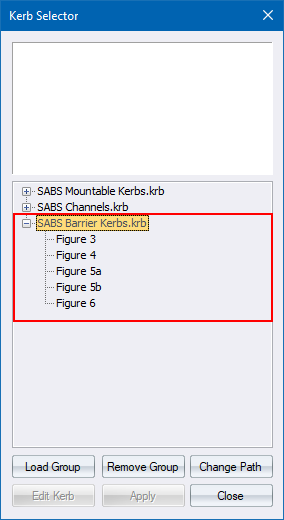
Now select the Figure 6 kerb and
click Apply.
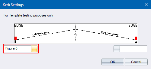
- The Kerb Settings are updated to show your choice of kerb for the
left edge.
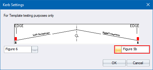
- Now click on the right ...
and select a Figure 8a Mountable kerb for the right edge in a similar
manner. You need to load the Mountable Kerbs into the Kerb Selector.
- Click OK to return to the
Template Editor.
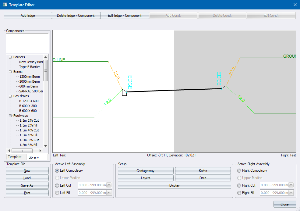
Notice how the display area is updated to
show the left and right kerbs.
- Now add a 1.5m walkway to the left edge. This will be a compulsory
addition, so select the Left Compulsory
radio button in the Active Left Assembly group.
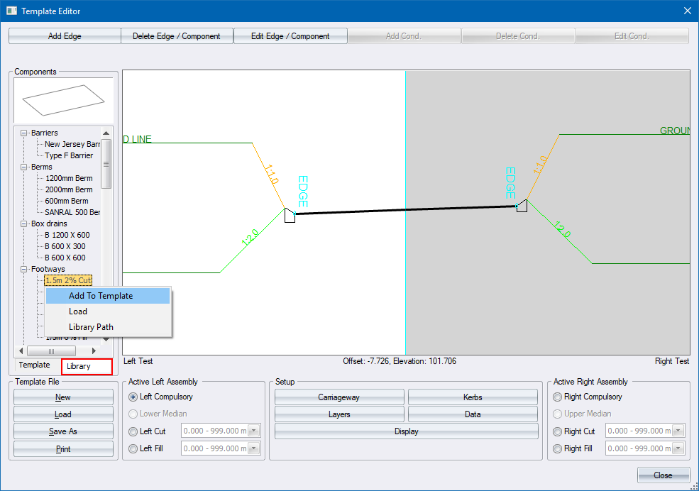
- Thereafter, click on the Component Library tab and select the 1.5m
2% Cut feature in the Footways component group. Right-click on this
component and select the Add To
Template option.
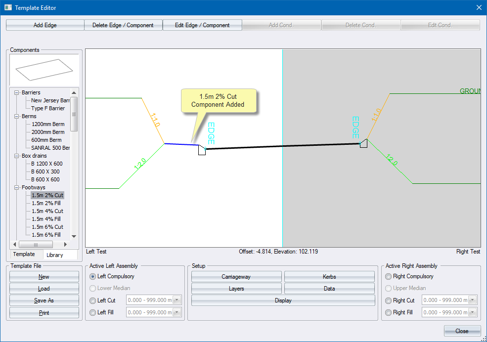
- The component is added to the left kerb and the display area is
updated.
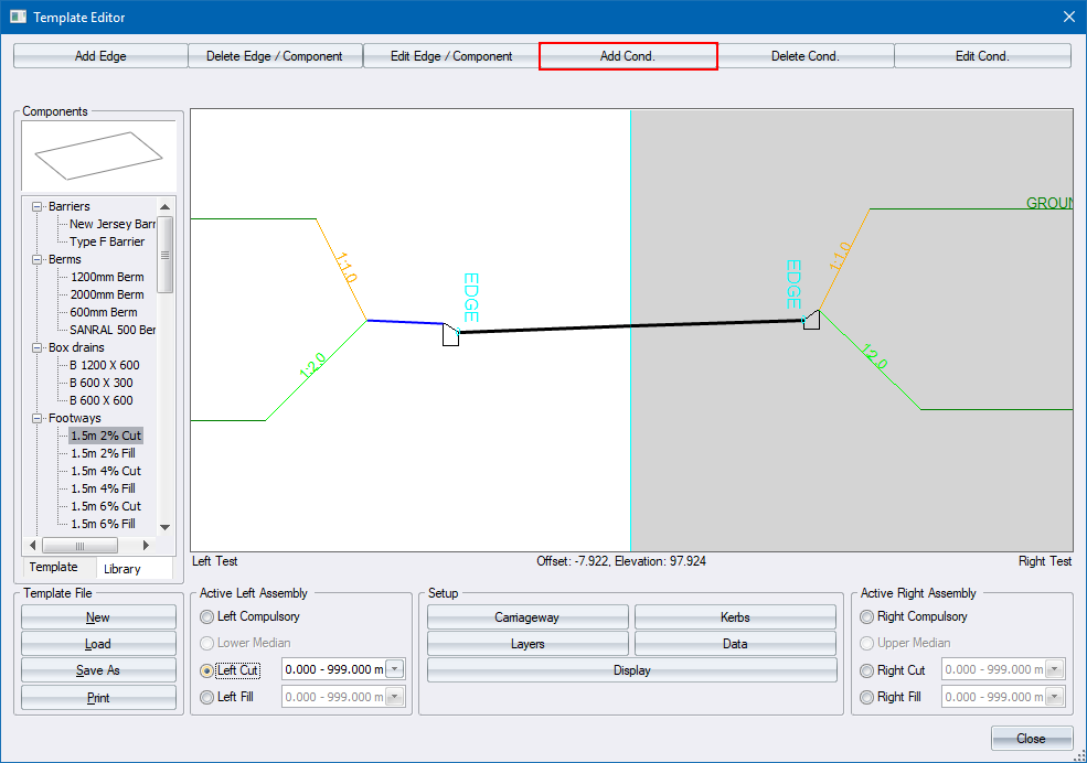
Cut Profile
To add a left cut condition:
- Select the Left Cut radio
button.
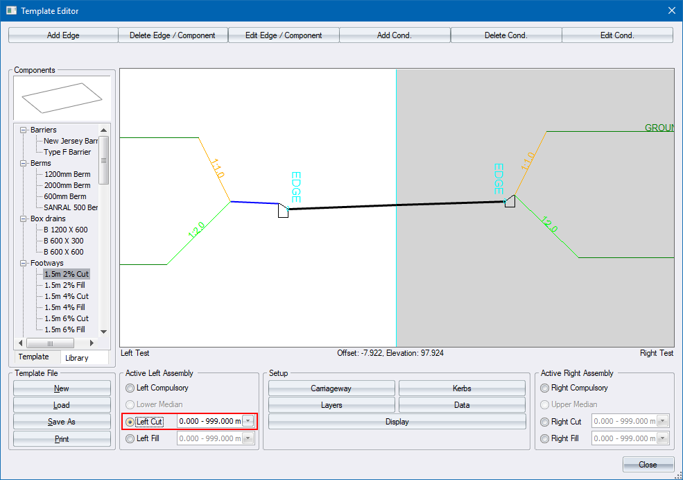
The list on the right of the button shows
that this cut condition is applicable from a depth of cut of 0m to 999m.
In other words, it is applicable for all cut conditions.
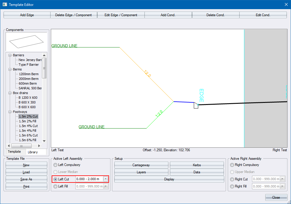
- Create a new cut condition from 0 to 2.0m and specify a cut slope
of 1:2. Do this, click Add Cond.
at the top of the Road Template.
- The cut
parameters display. Change the value so this condition is only
applied over the 0 - 2m depth range by typing in a value of 2.0 in
the Max Height box. Click OK.

- The template display updates and the height range for the Left
Cut is updated to show the amended range from 0 - 2.0m.
- Select the 2.0 to 999.0 cut condition in the Left
Cut box.
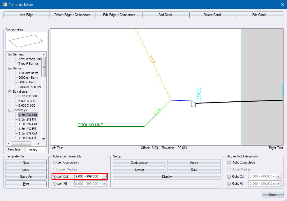
- Now click Edit Cond. at
the top of the Template Editor.
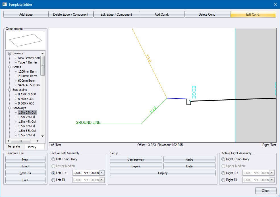
- The Left Cut conditions are shown for the 2.0 - 999.0m height range.

- Change the Slope to 1.5 and click Enter
 .
.

- This then uses a cut slope of 1:1.5 if the depth of cut is more
than 2m. If the depth of cut is less than 2m, the previous cut profile
is applied.
Specify a Minimum Toe Point Distance with Variable Slope
To change the 0-2m cut profile to apply a variable slope so that the
toe point is a constant distance from the road centre line:
- Specify the required offset, often the distance from the centre
line to the road reserve, and change the offset type to Min.
This tells the program to apply a variable slope between 0 and 1:2
so the toe point is at the required offset.
