Create new, or edit existing, road templates. See the Road Templates section for more details on templates.
Option
|
Description |
||||||||||||||||||||||||||||||||
Edge/Component buttons |
The Edge/Component buttons allow you to add, delete or edit an existing edge or component from a compulsory, median or cut/fill assembly.
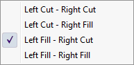
When adding or editing an edge, the special vertical movement codes can also be input via the dropdown list of the Ver. list box:
An optional Point Control Name can be specified. This is any unique identifier that can be used when specifying Point Control rules in the Point Controls dialog. You can specify the same Point Control Name in multiple templates. Point controls are only applicable to Strings Roads and will have no effect on cross-section roads. |
||||||||||||||||||||||||||||||||
Condition buttons |
The Condition buttons allow you to add, delete or edit an existing cut or fill condition.
|
||||||||||||||||||||||||||||||||
Components |
This area displays the available components in the template library path. Components are items such as side drains, sidewalks, retaining walls or catchwater berms that are added on to the active assembly. They are created and modified in the Component Editor.
There are two tabs:-
Once a component has been added to the template from the library, it will be listed in the Template section. You can edit the components in the Template list, which will change the component in the active template only.
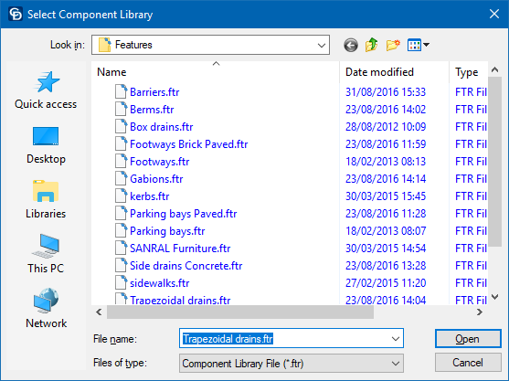
Use the Load option to add a component file from any other folder to the list. Use the Library Path option to change the library path, which lists all the component files in the specified library folder.
|
||||||||||||||||||||||||||||||||
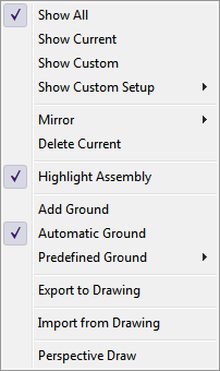
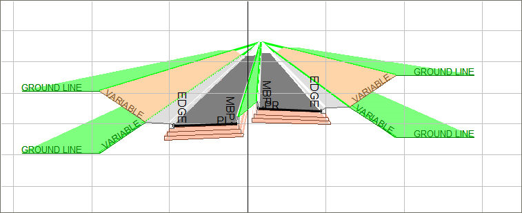
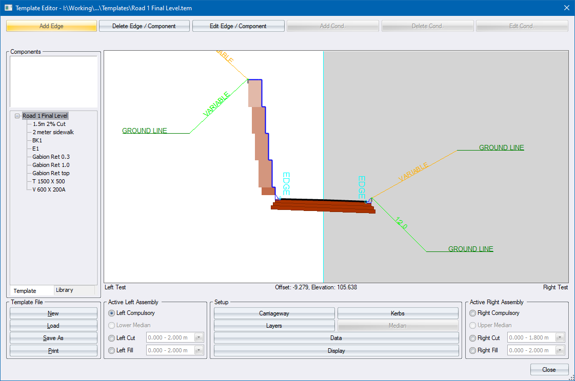
Display Area |
This area displays a graphical representation of the template. Right-click to display various options.
|
||||||||||||||||||||||||||||||||
Template File |
|||||||||||||||||||||||||||||||||
New |
Click to create a new template file. This clears all current entries. You will be given the option to save the current template if it has been changed. |
||||||||||||||||||||||||||||||||
Load |
Click to load an existing template file. You are given the option to save the current template if it has been changed. |
||||||||||||||||||||||||||||||||
Save As |
Click to save the template to a new template file. |
||||||||||||||||||||||||||||||||
Click in order to generate a listing of the current template details. |
|||||||||||||||||||||||||||||||||
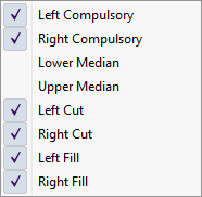
Active Left Assembly |
|||||||||||||||||||||||||||||||||
Left Compulsory |
Select this option to add to or edit the left compulsory additions. |
||||||||||||||||||||||||||||||||
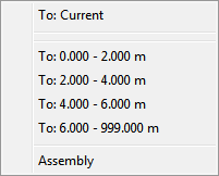
Left Cut |
Select this option to add to or edit the left cut condition(s). If more than one height range has been defined you can select the relevant height range from the list. |
||||||||||||||||||||||||||||||||
Left Fill |
Select this option to add to or edit the left fill condition(s). If more than one height range has been defined you can select the relevant height range from the list. |
||||||||||||||||||||||||||||||||
Setup |
|||||||||||||||||||||||||||||||||
Carriageway |
Display the Carriageway Setup. Here you can specify if the road is a single or dual carriageway, as well as the widths and cross falls. |
||||||||||||||||||||||||||||||||
Kerbs |
Display the Kerb Settings where you can load and select kerbs from the kerb library. |
||||||||||||||||||||||||||||||||
Layers |
Display the layer settings in the Data Setup spreadsheet. |
||||||||||||||||||||||||||||||||
Data |
Display the Data Setup spreadsheet showing the active assembly detail. |
||||||||||||||||||||||||||||||||
Display |
Display the template Display Settings. |
||||||||||||||||||||||||||||||||
Export |
Export the template as a .DR4 or .DWG drawing file. |
||||||||||||||||||||||||||||||||
Right Active Assembly |
|||||||||||||||||||||||||||||||||
Right Compulsory |
Select this option to add to or edit the right compulsory additions. |
||||||||||||||||||||||||||||||||
Right Cut |
Select this option to add to or edit the right cut condition(s). If more than one height range has been defined, you can select the relevant height range from the list. |
||||||||||||||||||||||||||||||||
Right Fill |
Select this option to add to or edit the right fill condition(s). If more than one height range has been defined, you can select the relevant height range from the list. |
||||||||||||||||||||||||||||||||
Components are items such as side drains, sidewalks, retaining walls or catchwater berms that are added on to the active assembly. The Component Editor allows you to set up and use a predefined set of components, which can simply be added in or inserted into a template. You can also define new components and modify existing components.
 You can
only add or insert a component at the start or end of an existing component
or assembly.
You can
only add or insert a component at the start or end of an existing component
or assembly.
The Components section has two parts - Template and Library.
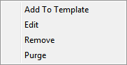
This section lists the components that form part of the template. You can access the following options with the right-click menu.
Option
|
Description |
Add to Template |
To add a highlighted component to the end of the active assembly select the Add to Template option. |
Edit |
Select the component you want to change and select the Edit option. The Component Editor displays so you can change the name or the geometry of the component.
|
Remove |
Only available if the selected component is not used in the template. Removes the selected component from the template file. |
Purge |
This option removes all components that are not referenced in the template. |
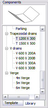
This section lists all the components in the active component library. The component list is a tree structure that can be collapsed or expanded by clicking + and - , respectively.
Option
|
Description |
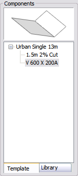
Display Area |
A graphical representation of the selected feature. |
Component list |
The list of components that have been loaded. You can add additional component sets using the Load option. |
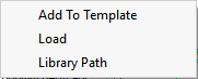
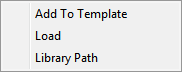
You can access the following options with the right-click menu.
Option
|
Description |
Add to Template |
Select to add a highlighted component to the end of the active assembly. |
Load |
Allows you to load an external component file into the component library. |
Library Path |
Select a different component library. |
To add a new component group, say "Retaining systems", select an existing component group, right-click and select the Load option.
You can import the definition of a component from an active drawing. This allows you to specify edges from any CAD drawing containing lines and polylines.
See Also Pavement Layer Designer, Template Editor