Components can be created by specifying horizontal and vertical offsets, or by indicating lines in an existing drawing.
Components are always specified as if they are added to the right of the template. In other words, the component is specified with positive offsets. When you add a component to the left of a template, the component's offset values are negated and therefore the component is mirrored about the vertical axis.
Change to Roads mode.
Select Tools ► Component Editor from Roads Mode.
Click Add.

Enter a component name of “Retaining wall 6m” for the component you are going to create, and then click OK.

Right-click in the Geometry grid and select Import from Drawing from the right-click popup menu.

You are prompted to:
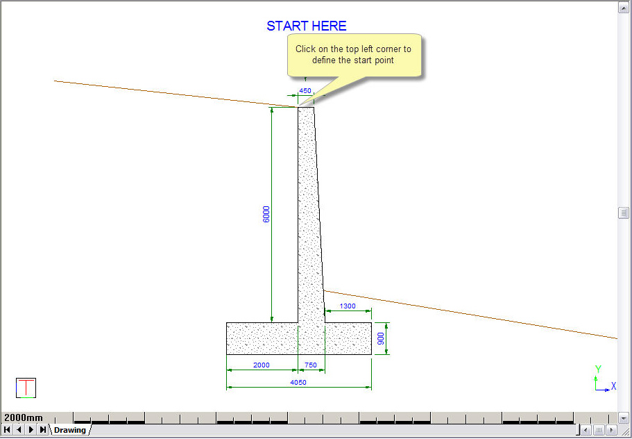
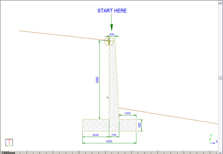
Indicate Start Point of Component
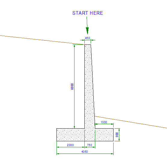
To define the start point, click the top left corner of the feature outline (in black) directly under the text that says START HERE. The start point is where this component ties in to the previous point (taken towards the centreline) on the road profile. In this instance you are specifying a retaining wall to be used in a fill condition, i.e. the road surface is on the left and at the top of the retaining wall.
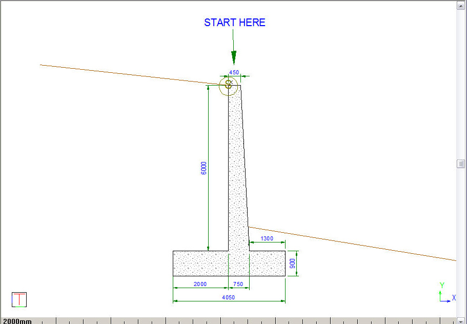
The start point is identified and labelled.
You are prompted to:
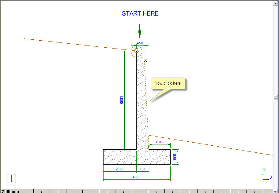
Indicate Next Entity of Component (Right click to Finish)
Now click on each of the feature lines around the retaining wall in a clock-wise direction. As you indicate sides, the S label is updated to the end of the indicated lines.
Continue indicating the outline of the retaining wall until the entire perimeter has been defined.
Right-click and select the Replace option.
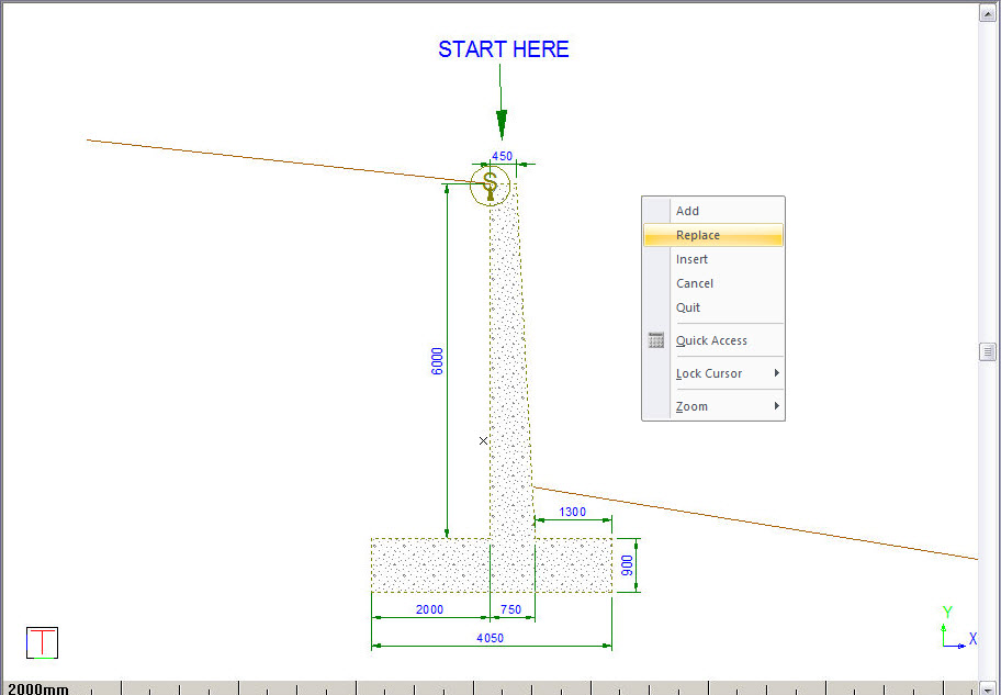
The component is added to the Component Editor.

Select the Stop checkbox in line 3 to indicate where the next component or cut/fill slope should tie in to this component.

Select the Cross-section tab. In this tab you can specify where the cross-section will be generated during Apply Template. This is indicated by the red lines.

Change the Method to Above.

Select the Quantities tab to specify additional quantities that you want calculated. By default, the program lists the linear length of the components used during quantity calculation. You want to add the following:
Volume of the concrete footing of the structure.
Volume of the concrete wall.
Backfill quantity behind the wall.
Define the Volume quantity for the Footing as follows: Select Type = “Volume”.

Right-click in the Formula column and select the Define Region from the right-click popup menu.

Define the region shown below by clicking on the sides of the footing. When complete, right-click to return to the table. You can now enter a description of “Footing Volume”.

Repeat to define the wall volume as follows:

For the backfill, you want the program to calculate the following volume:
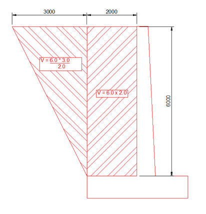
Specify an Area quantity type and specify the region as follows:

The volume for the rectangular portion above the footing is the length of side {7} multiplied by the height of 6.0.
Now add the formula for the 3 x 6m triangle.

Close the Component Editor and save.