Option
|
Description |
Display Area |
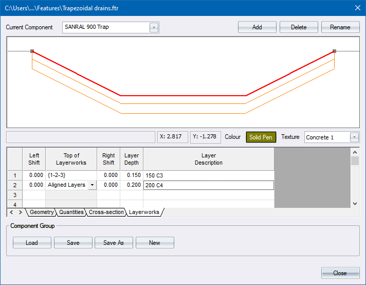
A graphical representation of the selected component. |
Current Component |
Select the current component from the list. |
Colour |
Set the colour the component will be drawn in. |
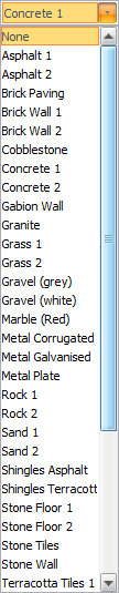
Texture |
Set the texture that will be applied to the component in Render view.
|
Geometry |
A spreadsheet of component coordinates that define the geometry of the component. As you type in or edit coordinates, the display area is updated. |
Quantities |
Specifies how quantities will be calculated for this component. |
Cross-Section |
Specifies what should be used in calculating the earthworks cross-section. |
Layerworks |
Defines the layerworks for the component. |
Add Feature |
Click to create a new component. |
Delete Feature |
Click to delete a component from the component group. |
Rename Component |
Click to change the name of an existing component. |
Component Group |
|
Load |
Load a component group from a file. |
Save |
Save the current component group. |
Save As |
Save the current component group to a new file. |
New |
Create a new component group. |
Specifies the cross-sectional geometry of a component by using two dimensional vectors.

Option
|
Description |
Hor column |
Specifies a horizontal movement. The dropdown list includes the following options:
|
Vert column |
Specifies a vertical movement. The dropdown list includes the following options:
|
Stop |
Indicate where the next component or cut/fill slope must start. |
Specifies how quantities will be calculated for this component. The program automatically multiplies the specified quantities by the length of the component.

Option
|
Description |
Type |
Enter the type of quantity to be calculated:
|
Formula |
Enter the range - closed polygon for Volumes; and open polygon for Areas. You can also add, subtract, multiply or divide a constant value to the range. Right-click and select the Define Region option to indicate sides on the component profile.
|
Description |
Enter a description that will be printed when running component volumes. |
Specifies what should be used in calculating the earthworks cross-section.

Option
|
Description |
Method |
Specifies how the region representing the earthworks cross-section is calculated.
|
Region |
Indicates the region. Use a polygon to create the earthworks cross-section. Right-click and select the Define Region option to indicate sides on the component profile for the Custom Method. |
Stop on grade |
Optional value that is used to automatically calculate the stop point using the previous grade. Maintains the method used for Region. |
This section defines the layerworks for the component. Entries consist of the left and right optional shifts from the component limits in order to create a stepped layer, the depth of the layer and a description of the layer.
Right-click to access the Pavement Designer.

Option
|
Description |
Left Shift |
Optional value that is used to widen or narrow the left side of a particular layer. |
Region |
|
Right Shift |
Optional value that is used to widen the right side of a particular layer. |
Layer Depth |
Specifies the thickness of a particular layer. |
Layer Description |
Specifies the description that is displayed when running Component Layerwork Quantities. |