 Your layout won't necessarily look like this as we have enabled a number of optional items in order to pack the maximum amount of information into the image.
Home > Tutorials > Tutorial 1 - Screen, Mouse & Keyboard
This section describes the various components that make up the screen. These are the:
Title Bar
Menu Bar
Prompt Area and Control Bar
Line Type Display
Layer Display
Toolbars
Drawing Area
Smart Cursor Help
Coordinate Display
Mouse
Keyboard
The screen is divided into several parts, as shown below.
Your layout won't necessarily look like this as we have enabled a number of optional items in order to pack the maximum amount of information into the image.
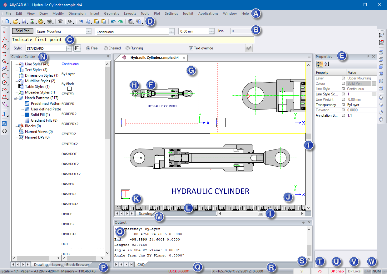
Specific areas of importance are explained below:
|
Marker
|
Screen Element and Description |
|
Menu Access various program functions by selecting menu items. |
|
|
Pen, Layer, Linetype, Width and Height These are buttons, combo boxes and edit fields where you can change drawing settings on the fly. |
|
|
Prompt/Control Bar Area This area displays prompts while working or, for more complicated procedures, displays a combination bar consisting of its own prompt area and various buttons, etc. for configuring settings while working. |
|
|
Toolbars These are user-defined bars containing shortcut buttons for the various functions. Toolbars can be docked on any edge of the main window, or can be floating. If the mouse cursor is hovered over a toolbar button, a help description for that button is displayed in the Status bar and, if held over the button long enough, a tooltip window also displays. |
|
|
Properties Bar This is used to quickly change various properties of the currently selected entity or entities. If no entity is currently selected, the property bar shows and enables changes to the current drawing settings (Pen, Layer, Linetype, Width and Height). |
|
|
Drawing Area This is where all drawing takes place. If the drawing area is subdivided into view ports then the active viewport, which is the one you can draw in, is outlined in yellow. |
|
|
Paper Border This indicates the extent of the defined paper. You would normally draw within this paper extent in order to correctly position your drawing when printing. |
|
|
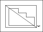
Last Snap/Jump Indicator This cross marks the last position where some sort of snap or jump was completed. It will be the start position when moving the drawing cursor via the arrow keys or a polar jump. |
|
|
Scrollbars Use the scrollbars to pan the drawing vertically or horizontally, by half the screen for every click. |
|
|
Drawing Plane Indicator This is similar to the View Plane Indicator except that it uses coloured arrows to indicate the relevant axes. It relates to the plane on which drawing is currently taking place, which is not necessarily the same as the view plane. For instance, the view of a house might be set to the Southeast corner but you want to draw a door in the left side wall. In this case, the drawing plane would be set parallel to the wall and therefore does not match the view plane. |
|
|
View Plane Indicator Being a 3D CAD, your view of the drawing can be rotated to any angle. This indicator, which is a cube with sides marked T (for top), F (for front) and L (for left), gives you an idea of the current rotation of the drawing axes. |
|
|
Ruler This gives an indication of the current scale of the drawing, or the active view port. |
|
|
Drawing/Layout Tabs Each drawing allows one drawing page and multiple layout pages. Layout pages are used for printing, and normally contain some sort of view of the data in the drawing page. These tabs are used to switch between the drawing page and any existing layout page. Right-clicking one of these tabs opens a menu with options to insert new layout pages or to delete existing layouts. |
|
|
Control Centre This bar displays information relating to the current drawing. |
|
|
Output Bar This bar is used to display information relevant to certain tasks carried out. |
|
|
Scale/Paper Indicator AllyCAD works in a particular scale on a particular paper size, which are both user selectable. This indicator is just a reminder of what scale and paper size have been selected. |
|
|
Lock Indicator The current cursor lock angle, if any, is displayed here. |
|
|
Cursor Coordinate This displays the current position of the mouse or digitiser cursor in X (horizontal), Y (vertical) and Z (elevation) planes. |
|
|
Filter Toggle This toggles the selection filter on or off. When toggling on, the entity selection filter is displayed which allows you to specify in detail what types of entity may be part of a selection set. |
|
|
Visual Snap Toggle This toggles the display of the Visual Snap indicator. When using a drawing function in conjunction with a snap mode (other than Freehand Snap) with this toggled on, a small marker is displayed to indicate where the snap point would be if you clicked on the mouse button or the first digitiser button. |
|
|
DP/3D Snap Toggle This toggles between snapping on the current drawing plane (DP) and snapping to a 3D coordinate. Normally the snap modes pick up the current elevation from the entity on which the snap is made. With DP snap toggled on, the elevation is determined by projecting the snap point onto the DP. |
|
|
DP/World Coordinate Toggle This toggles the Cursor Coordinate between displaying coordinates relative to the current drawing plane and true 3D coordinates. |
|
|
Keyboard Indicators Shows whether Caps Lock and Num Lock are on or not. |
Prompts display in the prompt area asking for input or telling you what to do. You type information, answer questions or select options in the Control Bar. There are several types of prompts and responses.

If you are prompted to enter a point or a position, for example the first point of a line:
Position the cursor in the Drawing Area.

Some prompts expect you to type information into the Control Bar.
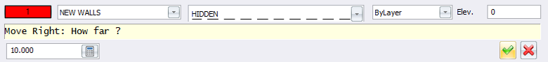
In this example, the program is asking how far you want to move to the right after you have pressed the [Right Arrow] key. A default answer 10 is given.
If you want to accept the default answer, click OK  or press [Enter].
If you want to change the default answer, simply type the answer you want. If the default answer is highlighted, it is automatically overwritten.
Alternatively, click in the white part of the Control Bar and press [Arrow] and [Backspace] to delete the default answer. Now type the answer and accept it by clicking OK or pressing [Enter].
If you want to terminate the function, click Cancel  .
.
When you select some functions, a row of options appear on the Control Bar. You need to edit these options to your satisfaction before responding to the prompt in the Prompt Area.
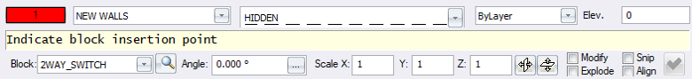
In this example, you need to select a symbol or block - either by name or by viewing it, and then specify the rotation, scale, mirror and snip options of the symbol.
Indicate block insertion point
Position the cursor where you want the symbol to appear and press [Enter] or click to accept this position.
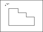
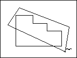
In many functions, such as Select by Polygon, Stretch, etc, you are asked to enter a polygon around something. The function then operates on the part of the drawing inside this polygon. You can either draw a regular box around the part of your drawing to be operated on, or, if it is an irregular shape you can draw an irregular polygon around it.
To draw a regular box:
Indicate polygon around elements to be selected
You are prompted to:
Indicate next point of polygon (Right-click to finish with rectangle
Right-click and select the Finish option from the popup menu.
The function you are using resume.
To draw an irregular polygon around the part of the drawing to be operated on:
Indicate polygon around elements to be selected
Indicate next point of polygon (Right-click to finish with rectangle)
You are prompted to:
Indicate next point of polygon (Right-click to finish with rectangle)
Indicate next point of polygon (Right-click to finish with rectangle)
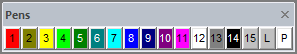
To change the current pen, or colour:
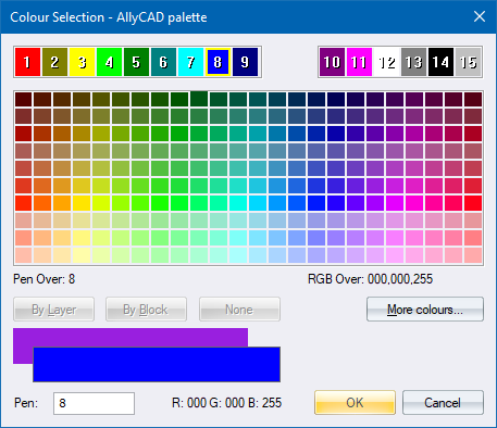
Select a colour from the displayed palette or click More colours… to define a custom colour from the full range supported by the operating system.
You can specify which palette you want to use in the System Settings option. Choices include AllyCAD, AutoCAD, Microstation, Caddie and Ultimate CAD. The palette is only available on new drawings.
You can also change the palette in the View Settings option. The palette selection is saved with the drawing.
Many colours won't display properly unless your graphics card is set to display 32 bit colour, also known as TrueColor.
The Line Style Display displays the currently selected line style. To change line style:
Click the arrow to the right of the display. A list of line styles displays.

If you select the By Layer option, the program uses the line types assigned to each layer in the Layer Settings option.
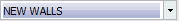
The Layer Display displays the currently selected layer. Everything that you draw appears on this current layer. To change the current layer:
Click the arrow to the right of the display. A list of layers appears.
There are 24 toolbars, which can be displayed and positioned selectively.
Select View ► Toolbars, or click the toolbar icon ![]() , to select which toolbars must be visible. A list with the names of the toolbars is displayed. Those that are currently visible have a tick next to them.
, to select which toolbars must be visible. A list with the names of the toolbars is displayed. Those that are currently visible have a tick next to them.
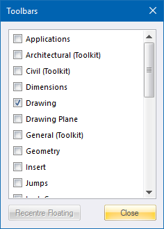
Select or deselect the checkbox next to the names to display or hide the relevant toolbars.
If you have made a toolbar visible you can position it anywhere on the screen. If you drag the toolbar very close to an edge of the screen, you see that it changes to align itself to that edge. Release the mouse button to dock it in that position.
Each icon in the toolbars represents a shortcut to a function. As you move the cursor over a button on a toolbar, a tooltip displays explaining the functions assigned to the button. The Smart Cursor Help on the Status Bar at the bottom of the CAD window also tells you what it does.
You can customise the toolbars using the Toolbar Editor.
The keyboard and mouse are both used when drawing with Civl Designer 8.0.
The keyboard is used to input data, for example distances to move, coordinate to move to, measurements, text, etc. There are also a number of keyboard shortcut options or accelerator keys that can be used to activate functions in Civl Designer. The function assigned to each key is specified in the Cad.acc file. Use the Accelerator Editor to customise the shortcut keys.
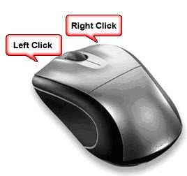
The mouse offers both left and right-click options. The left-click is the standard selection method.
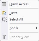
If you right-clicked on the screen with no functions selected, you are presented with the following popup menu.
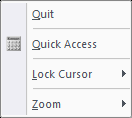
If you right-click when a draw function is selected, you are presented with the following popup menu.
The mouse wheel allows you to zoom in and out. If you roll the Mouse Wheel forward it zooms in on the area where the cursor is positioned. If you roll it backwards it zooms out about the area the cursor is positioned.
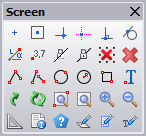
Double-click the mouse wheel to display the Screen toolbar displayed below.
Depress the mouse wheel and hold it down to pan the drawing around the position of the cursor.