Icon
Command
Shortcut Key
Toolbar
![]()
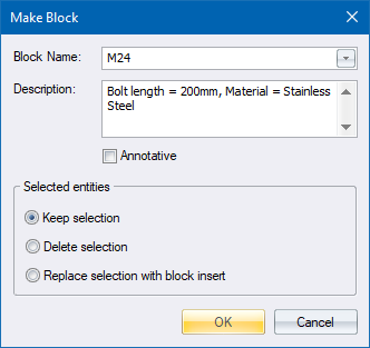
MAKEBLOCK
Tools
Home > CAD Mode > Tools > Blocks > Create Block
Create a block object from entities in a drawing.
|
Icon |
Command |
Shortcut Key |
Toolbar |
|
|
MAKEBLOCK |
|
Tools |
A block is a group of entities that you can name and insert or re-use in one or more drawings.
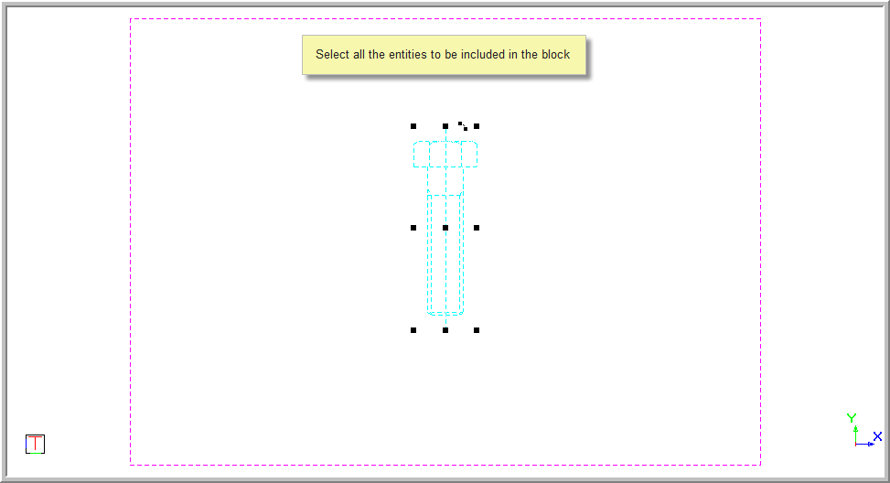
Make a block object from entities in a drawing by selecting them, naming the block and indicating the "base point" (reference point) of the block.
 Attributes included in the selection will become block attributes.
When you create a block definition from entities in the drawing, and the current Drawing Plane (DP) is not set to Top View, then the block created will be oriented with respect to the current DP. The Z axis of the current DP will determine the front of the block definition i.e. the current DP coordinate system will be used as the block's coordinate system.
Later, when you insert this block, the front of the inserted block will be in the direction of the DP at the time of insertion i.e. the inserted blocks' axes will be set to the current DP's axes.
Save frequently used blocks to a symbol library, for use in other drawings.
Procedure
To create a block:
Annotative scaling is not applied to nested blocks (blocks within blocks), nor is it applied to annotative attributes within annotative blocks.
Select Keep selection if you want the selected entities for the blocks to remain selected once the block has been created.
Select Delete selection if you want the selected entities to be removed from the drawing once the block is created.
Select Replace selection with block insert if you want the selected entities to be removed from the drawing, and a block insert referencing the new block to be added to the drawing to replace the deleted entities.
Click OK to create the block; or Cancel to quit the function.
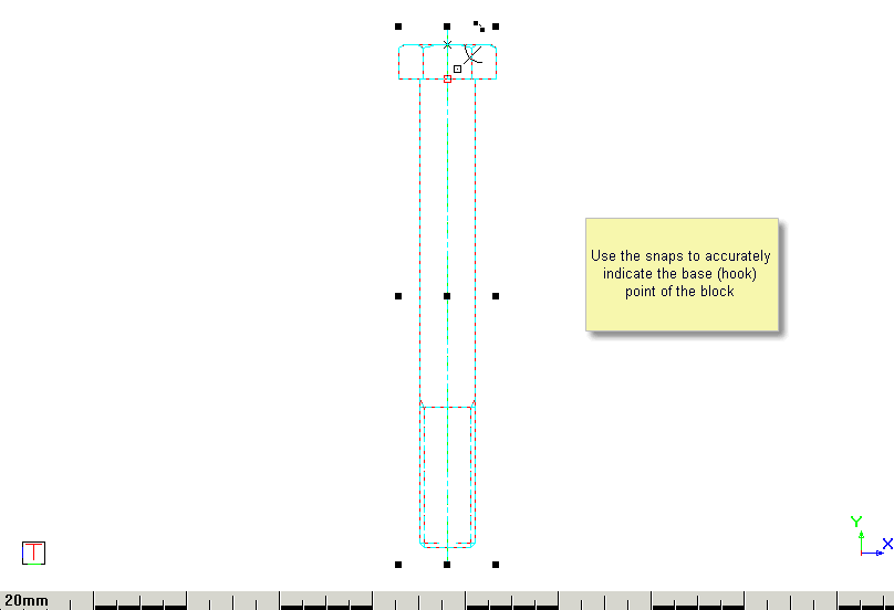
Indicate base point of block
The base point (insertion point) is the hook point in earlier versions of Civil Designer.
The entities from which the block will be created have been drawn in the Left View (note the view axis indicator).
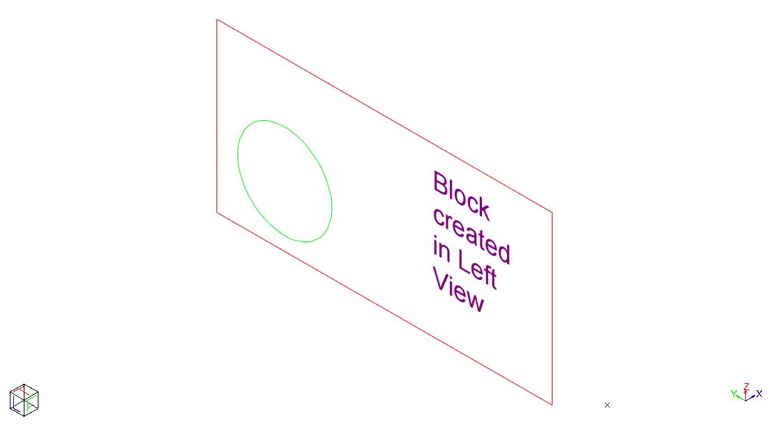
The DP is set to the Left View (note the DP axis indicator above), the relevant entities are selected and the block is created.
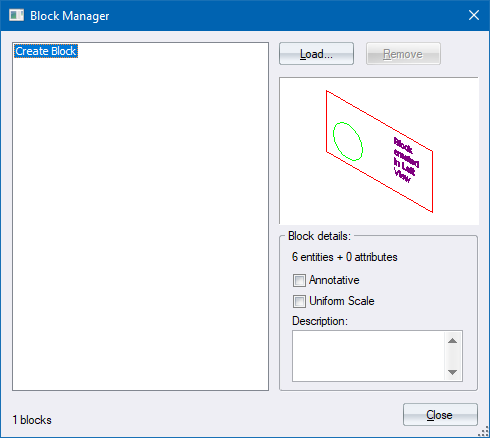
After the block has been created it can be viewed in the Block Manager.
Note that the block preview always views the block from its "front".
The DP is now changed to Left View and the block inserted into the drawing.
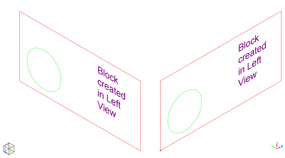
Note how the front of the inserted block (on the right) is in the direction of the current DP axis.
Until you are comfortable with the concepts of 3D blocks, it is recommended that blocks are created in Top View/DP wherever possible.