Home > Roads Mode > Alignment > Vertical > Edit Alignment
Edit the vertical alignment.
|
Icon |
Command |
Shortcut Key |
Toolbar |
|
|
RD_VERTICALEDIT |
|
|
This function allows you to enter or edit the vertical alignment for the road into the spreadsheet. The vertical alignment is stored in ASCII format in the design file of the active road. The Graphical View option displays a longsection of the vertical alignment.
Two vertical alignments must be specified for dual carriageway roads - one for the left carriageway and one for the right.
Select the carriageway using the tabs at the bottom of the spreadsheet.
Select Single/LHS for a single carriageway; or the left carriageway of a dual carriageway road and RHS for the right carriageway of a dual carriageway road. The two alignments are graded separately. If both carriageways are to follow the same alignment, the Left carriageway should be entered and then be duplicated on the right by copying and pasting the relevant data.
In the case of a single carriageway road, the alignment is taken from the Single/LHS spreadsheet only.
A road is recognised as being a dual carriageway by the fact that it has two vertical alignments (possibly identical). All later functions, such as Edge Levels and Apply Templates, depend on this recognition of a dual carriageway road in order to present the correct options.
Procedure
The Vertical Alignment window will be displayed. There are 2 view tabs on the left of the window:
The vertical alignment data displays in the spreadsheet.
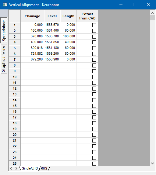
Vertical curves are defined in terms of chainage, VPI elevation and curve length for parabolic curves; and radius for circular curves. The shape of the curves can be set in the Design Criteria. The chainage and elevation for the start VPI must be specified with a curve length of '0'. The intermediate VPIs follow with their chainage value, elevation and curve lengths.
Kinks in the alignment can be created by entering '0' for the curve length. The alignment is ended with an end VPI that has a chainage, elevation and a curve length of '0'.
To put in a non-symmetrical vertical curve, enter a negative curve length with the fractional part of the length representing the percentage of the curve length to be allocated to the first portion of the curve. For example, if a curve length of 60 metres is required with 40 metres being allocated before the VPI and 20 metres after it, the curve length should be entered as '-60.66' (40/60 = 0.66).
The vertical alignment is displayed as a longsection, with options to add, delete, edit and move VPIs.
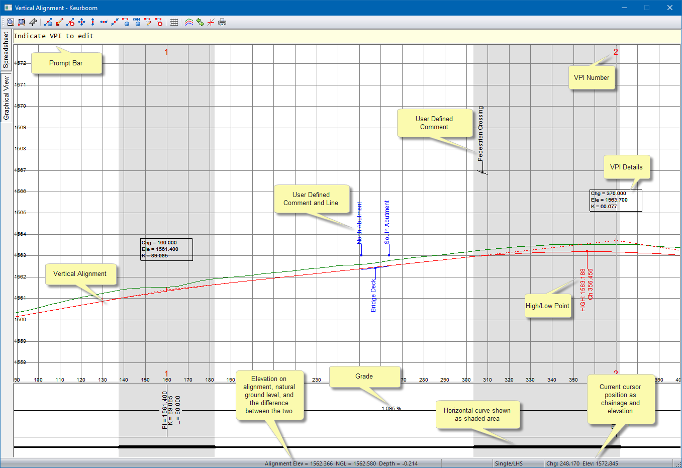

The toolbar at the top of the graphical view allows access to a number of setup and editing functions.
|
Icon
|
Description
|
|
|
Redraw. |
|
|
Zoom Window. |
|
|
Change the vertical exaggeration. |
|
|
Insert a VPI. |
|
|
Edit an existing VPI. |
|
|
Delete an existing VPI. |
|
|
Move an existing VPI. |
|
|
Move an existing VPI up or down. |
|
|
Move an existing VPI horizontally. |
|
|
Move an existing VPI along the grade. |
|
|
Add a user-defined line. |
|
|
Add a user-defined comment. |
|
|
Edit a user-defined line or comment. |
|
|
Delete a user-defined line or comment. |
|
|
Grid display settings. |
|
|
Ground line display settings. |
|
|
Toggle carriageway. |
|
|
Track the cursor position on the horizontal alignment. |
|
|
Print. |
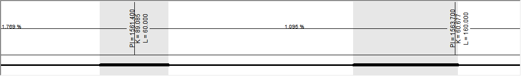
An Information Bar is displayed at the bottom of the graphical view. A line at the bottom of the Information Bar shows the horizontal alignment. Thick parts in the line represent horizontal curves, while gaps in the line represent transition curves. Only the curve information for the active carriageway displays.
The Prompt Bar displays prompts for certain functions.
Indicate VPI to edit

As you move the cursor, the Information Bar displays the elevation on the alignment, as well as the ground level and the difference between the two at the cursor position on the left of the Status Bar. The chainage and elevation at the current cursor position are also be displayed on the right of the Status Bar.
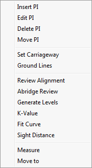
Apart from the graphical editing functions documented above, there are also a number of shortcut keys that can be used to manipulate the view or edit the alignment. Right-click to display the popup menu:
|
Option
|
Description |
|
Insert PI |
Insert a Vertical PI. |
|
Edit PI |
Edit a Vertical PI. |
|
Delete PI |
Delete a Vertical PI. |
|
Move PI |
Move a Vertical PI. |
|
Set Carriageway |
Swap the active carriageway. |
|
Ground lines |
Display the Ground lines settings. |
|
Review Alignment |
Run Review Alignment. |
|
Abridge Review |
|
|
Generate Levels |
Generate Vertical Levels. |
|
K-Value |
Run K-Value. |
|
Fit Curve |
Run Fit Curve. |
|
Sight Distance |
Display the Sight Distance settings. |
|
Measure |
Measure the distance between two graphically indicated points. |
|
Move To |
Move to a specified point. Display the Cursor Jump. |
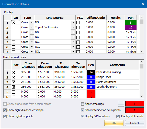
![]() - The Ground Line Details allow you to set additional information to be displayed on the screen.
- The Ground Line Details allow you to set additional information to be displayed on the screen.