
Home > Sight Distance Check Dialog
Specify the settings for the sight distance check.
Option
|
Description |
Eye height |
Enter the eye height of the driver. |
Object height |
Enter the height of the object the driver must be able to see over the minimum sight distance. |
Eye offset from CL / MBP |
Enter the offset of the driver from the centre line if the road is a single carriageway, or the offset from the median break point for a dual carriageway. |
Minimum Sight Distance |
Enter the minimum sight distance in m. This is the distance over which the driver must be able to see the object. |
Object offset from CL / MBP |
Enter the offset of the object from the centre line if the road is a single carriageway, or the offset from the median break point for a dual carriageway. |
Road Settings |
|
Start chainage |
Specify the chainage where you want the sight distance calculations to start. |
End chainage |
Specify the chainage where you want the sight distance calculations to end. |
Base Layer |
Specify the layer where the ground cross-sections are stored. |
Batter Layer |
Specify the layer where the final design cross-sections are stored. |
Road Reserve Settings |
Click to display the Road Reserve Settings. The Sight Distance check will fail horizontally if the line of sight crosses the road reserve. |
Dual Carriageway Settings |
|
Check on |
This option is only available for dual carriageway roads. Select the carriageway on which to do sight distance checking. |
Chain direction |
This option is only available for dual carriageway roads. Select the direction (Ascending or Descending) in which the sight distance checking should be done. For Single carriageway roads, the sight distance checking will be done in both directions automatically. |
No Sight envelope settings |
|
Ascending chain direction |
Enter the pen colour in which the program will indicate the areas where the driver can not see the object over the specified minimum sight distance in the ascending chainage direction. |
Descending chain direction |
Enter the pen colour in which the program will indicate the areas where the driver can not see the object over the specified minimum sight distance in the descending chainage direction. |
Horizontal Failure LT |
Select the line type to be used to mark areas where the sight distance check fails due to the horizontal alignment not allowing sufficient sight distance. |
Profile Failure LT |
Select the line type to be used to mark areas where a full 3D sight distance check fails. This will check if the sight line intersects with any cut bank, vertical curve or even berms and kerbs. |
Envelope to CAD |
Select this checkbox if you want the envelopes to be sent to a CAD layer as line segments. Type in the layer name. |
Show in Vertical Alignment |
Select this checkbox to display the no-sight envelope in the Vertical Alignment view. The envelope will be drawn on the vertical, as well as horizontal, alignments. If you are already in the Vertical or Horizontal alignment functions, this option will be disabled. |
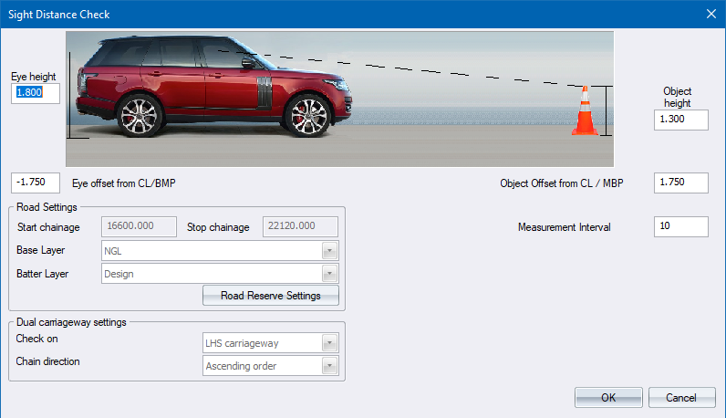
Specify the settings for the sight analysis.
Option
|
Description |
Eye height |
Enter the eye height of the driver. |
Object height |
Enter the height of the object the driver must be able to see over the minimum sight distance. |
Eye offset from CL / MBP |
Enter the offset of the driver from the centre line if the road is a single carriageway, or the offset from the median break point for a dual carriageway. |
Object offset from CL / MBP |
Enter the offset of the object from the centre line if the road is a single carriageway, or the offset from the median break point for a dual carriageway. |
Layer Settings |
|
Base Layer |
Specify the layer where the ground cross-sections are stored. |
Batter Layer |
Specify the layer where the final design cross-sections are stored. |
Road Reserve Settings |
Click to display the Road Reserve Settings. The Sight Distance check will fail horizontally if the line of sight crosses the road reserve. |
Dual Carriageway Settings |
|
Check on |
This option is only available for dual carriageway roads. Select the carriageway on which to do sight distance checking. |
Chain direction |
This option is only available for dual carriageway roads. Select the direction (Ascending or Descending) in which the sight distance checking should be done. For Single carriageway roads, the sight distance checking will be done in both directions automatically. |
Measurement Interval |
Specify the chainage interval along the road at which sight distance measurements will be taken. This value cannot be smaller than your coordination interval. |
See Also Sight Distance