Home > Cross-Section

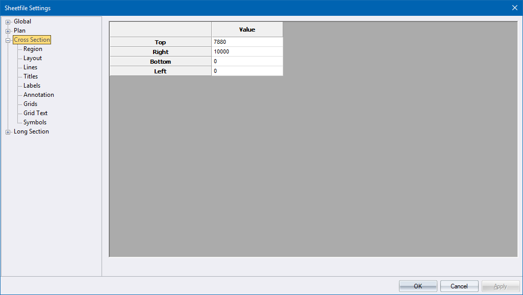
This section of the sheet file deals with the position and properties of cross-sections in a drawing.
 Note that all measurements entered in a sheet file are in 10ths of a millimetre, except where specifically indicated. Text heights will be correct for the original sheet file size but will change when the sheet file is scaled to fit other paper sizes when generating a plot.
|
Option
|
Description |
|
This page contains the limits of the cross-section plotting area in 10ths of a mm measured from the bottom left (0,0) of the global area. |
|
|
This page defines the layout of the cross-sections within the cross-section plotting region. It also sets the relationship of one section to another. |
|
|
This sub-section defines the lines on the cross-section drawing area e.g. datum line, centre line (CL), border, etc. |
|
|
This page defines the titles that are plotted only once on each page, and not at every section. |
|
|
This page defines text entities that will be written on each cross-section. |
|
|
This page defines text that is to be plotted on each section. The text values are extracted from the cross-section data of the various layers (the lines), as specified in the Cross-Section Setup. |
|
|
This page defines the cross-section grids. |
|
|
Specify the cross-section grid text parameters. |
|
|
You can insert symbols that have been loaded into the sheet file as blocks on the cross-section. |
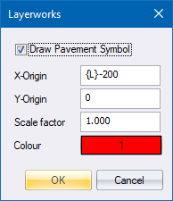
If you did a pavement design using the Pavement Designer, you can plot the pavement design symbol on the cross-section drawing.

|
Option
|
Description |
|
Draw Pavement Symbol |
Select this checkbox to display the Pavement Design symbol on the Cross-Section drawing. |
|
X-Origin |
The X-Coordinate of the bottom left-hand side corner of the symbol. |
|
Y-Origin |
The Y-Coordinate of the bottom left-hand side corner of the symbol. |
|
Scale Factor |
The symbol is scaled by this value when plotted. |
|
Colour |
The pen colour of the symbol. |