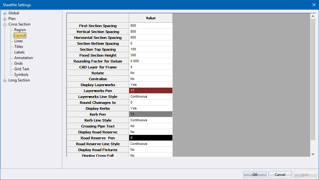
This page defines the layout of the cross-sections within the cross-section plotting region. It also sets the relationship of one section to another.
Label |
Option
|
Description |
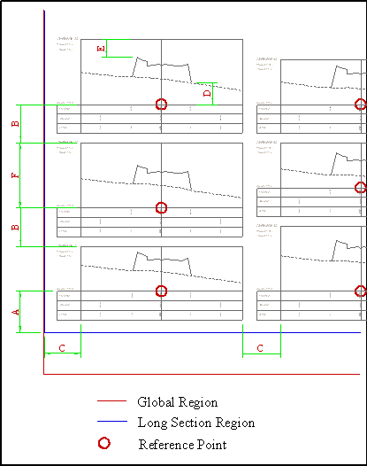
A |
First Section Spacing |
Enter the distance from the bottom of the plotting region to the origin of the first section. |
B |
Vertical Section Spacing |
Enter the distance between the top of one section and the origin of the section above it. |
C |
Horizontal Section Spacing |
Enter the distance between sections. |
D |
Section Bottom Spacing |
Enter the minimum distance from the datum of the section to the lowest point on the cross-section. |
E |
Section Top Spacing |
Enter the minimum distance from the highest point on the cross-section to the top. |
F |
Fixed Section Height |
The height of the section can be fixed or float. If the value is 0, each section will take up the minimum space possible, otherwise each section will be the height entered here. |
|
Rounding Factor for Datum |
Enter a value to which the actual cross-section datum must be rounded for the annotation. For a datum of 56m with a rounding factor of 10, the working datum will be 50. For a rounding factor of 5 the datum would be 55. |
|
CAD Layer for Frame |
Enter the CAD layer on which the frame should be drawn. |
|
Rotate |
Select whether the sections should be rotated through 90 degrees (Yes) or not (No). Right-click on the cell to toggle the option. |
|
Centralize |
Select whether the cross sections will be centralized horizontally within the plotting region (Yes) or not (No). This would normally be used on small plots where only one column of sections would be plotted. Right-click on the cell to toggle the option. |
|
Display Layerworks |
Select whether the layerworks specified in the relevant road template should form part of the cross section (Yes) or not (No). Right-click on the cell to toggle the option. |
|
Layerworks Pen |
Select the pen in which to plot the layerworks. Right-click the cell to display the pen selection. |
|
Layerworks LT |
Enter the line type in which to plot the layerworks. |
|
Round To |
Enter a rounding factor for cross sections to be drawn e.g. enter 100 to draw cross at 100m intervals. |
|
Display Kerb |
Specify whether the kerbs must be drawn on the cross-sections. Right-click on the cell to toggle the option. |
|
Kerb Pen |
Enter the pen colour for the kerb display. Right-click the cell to display the pen selection. |
|
Kerb LT |
Enter the line type in which to plot the kerbs. |
|
Crossing pipe text |
Right-click to toggle between Yes and No. If this option is Yes, then text will be displayed with crossing pipes on cross-sections. |
|
Display Road Reserve |
Specify if the road reserve must be plotted on the cross-section. |
|
Road Reserve Pen |
Specify the pen for the road reserve. |
|
Road Reserve LT |
Specify the line type for the road reserve. |
|
Display Road Fixtures |
Specify if road fixtures must be included on the cross-section. |