Home > Roads Mode > Alignment > Regression > Extract Alignments
Extract theoretical alignments from DTM, CAD lines or a strings model.
|
Icon |
Command |
Shortcut Key |
Toolbar |
|
|
RD_REHAB |
|
|
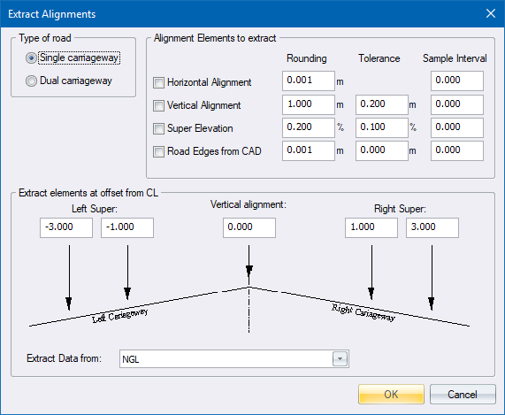
This function allows you to extract horizontal alignment, vertical alignment and superelevation data from a DTM surface, CAD lines or a strings model. These alignments can then be altered using the normal roads functions, after which a template can be applied.
Theoretical alignments include the following:
Horizontal Alignment - Comprises PIs and circular curves and spirals, which can be edited via the Horizontal Alignment spreadsheet.
Vertical Alignment - Comprises VPIs and parabolic curve lengths, which can be edited via the Vertical Alignment spreadsheet.
Superelevation Detail - Comprises chainages and superelevation slopes (percentages), which can be edited via the Edit Super spreadsheet.
You can also extract the road edges from CAD lines.
Procedure
If the Horizontal alignment checkbox in the Road Rehabilitation is checked, the program extracts a horizontal alignment from either a series of CAD lines or through control points. The alignment is written directly to the *.des file. Normal horizontal alignment functions can be used to edit the alignment subsequently.
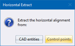
Select the source of the horizontal alignment data:
CAD entities - you are asked to indicate CAD entities that make up the horizontal alignment.
Control points - you are asked to indicate DTM points that define the straights and curves on the horizontal alignment.
You are prompted to:
Select the road centreline one element at a time. (Right Click to finish)
Select the CAD lines that represent the road alignment, one element at a time (Straight - Curve - Straight).
You are asked to indicate two points on every straight, and a point on each curve. The program then calculates intersections between the indicated straights (PI positions), and calculates the radii using the points on the curves.
You are prompted to:
Indicate the start PI
Indicate the start point of the road.
You are prompted to:
Indicate a point on the first straight
Indicate a point anywhere on the first straight, close to the first BC.
You are prompted to:
Indicate a point on the curve (Esc. to stop)
Indicate a point on the curve, somewhere close to the crest.
You are prompted to:
Indicate first point on the next straight (Esc. to stop)
Indicate a point on the next straight.
Indicate next point on the next straight (Esc. to stop)
Indicate another point on the straight.
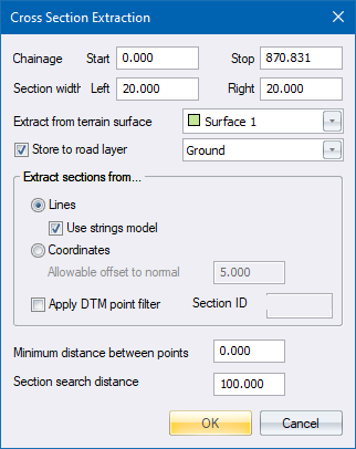
If the Vertical Alignment checkbox is selected, the program extracts the vertical alignment/s from the ground model. The calculated vertical alignment/s are entered directly into the *.des file.
Click OK to proceed.
The Cross-Section Extraction settings display to extract ground cross-sections.
The program enters into an iteration process to fit a vertical alignment onto the extracted ground cross-sections, using the Vertical accuracy setting as an indication of when to stop the process. The smaller the accuracy setting, the closer the alignment follows the ground, but the longer the process takes. A small tolerance also causes more small vertical curves.
After the iteration, the program checks for VPIs that exceed the Grade Tolerance, and removes them. The program then checks for overlapping vertical curves, and tries to fix them by reducing the curve lengths up to half the calculated length. If an overlapping Vertical curve can not be fixed, the user is notified by an entry in the Output window.
The following warning message displays.
If the Super elevation checkbox is checked, the road crossfall is picked up from the extracted cross-sections at the offsets specified in the Rehabilitation settings. A crossfall is picked up from every chainage, rounded and entered into the *.des file.
The Vertical alignment levels are generated.
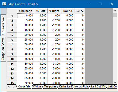
The program calculates and rounds crossfalls at every chainage. You can view the crossfall in the Edqe Level spreadsheet.
Finally, the Road Expert prompts you to generate edge levels and apply the template.