Track contours at any specified interval.
|
Icon |
Command |
Shortcut Key |
Toolbar |
|
|
TERRAINCONTOURLINE |
|
|
This function allows you to track contours at any specified interval, through a network of polygons connecting the terrain points.
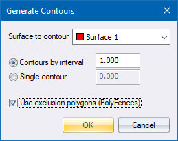
The layer to be contoured and the vertical interval have to be specified. Fractions such as '0.5' are permitted.
The function first locates the perimeter of the site. Once a perimeter has been located, the contours are tracked from the lowest possible elevation to the maximum elevation, at the specified interval. You must not have more than one site separate from each other on the surface to contour, because the perimeter will not be found and you'll get contours doubling back on themselves. Either move separate sites onto different surfaces or join the sites with breaklines.
Contours are stored in a file called Jobname.CNT.
Because this routine is based on polygons, the lines forming the polygon boundaries must have been previously created using Add Break Line, Add Feature Line, Intelli-Lines or Triangulate. The accuracy of the contours is directly dependent on these lines, so it is essential that the lines conform to the terrain surface as accurately as possible.
It is essential to join all the points on the perimeter of the portion of the site to be contoured. Once the operation starts, the first process is to locate the perimeter. If a "Perimeter failed" message displays, inspect the site to see where the tracking stopped, then carefully check the lines in that area. Look for crossed lines, single lines that go into space, or points that appear to be connected by lines but are in fact not joined, thereby creating a gap (the ID Point function is ideal for this). Duplicated data is a common criminal in this regard. Make sure all gaps are closed before generating contours again.
Areas within the site that you do not want contoured, e.g. buildings, water surface, etc, first need to be defined as polyfences. Then at the contour stage, select those polyfences as exclusion polygons and those areas won't be contoured. Keep the polyfences as simple as possible. For complex shapes, rather divide the area up into smaller simpler figures by adding additional break lines. Then define multiple smaller polyfences instead of one large one. At a later stage, after generating the contours, you can thrn remove these fictitious breaklines. In this way, you minimize the chance of getting unwanted parts of contours that erroneously cross the polyfence.
Refer to DTM contours for a discussion of the relative merits between generating contours from break lines, and generating contours from DTM information.
There are two potential hazards in generating Contours from lines:
As a contour is being tracked, if there is more than one possible exit from a polygon, the contour exits through the point closest to its entry point. This may not necessarily be correct.
If two lines on the surface being contoured cross each other, it produces two overlapping polygons. If this situation is encountered, the contours in that section are omitted so the user can make the correct connections by hand later on.
Both hazards can be overcome by using correctly formed polygons.
Always check your contours. Being a line-based system, the contours are in their theoretically correct positions but this only holds true if the line/polygon system is also correct. Of course it never is, and a bad break line results in erroneous contours. See the remarks under DTM Contours.
See Also Contours from Lines versus from DTM.
Procedure
Fill in the relevant data and click OK.
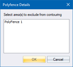
Select the polygons through which no contours should be drawn. Select multiple items by holding down [Ctrl] or [Shift] while you make your selection.
 The entire surface is operated on.