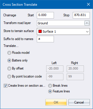
Specify the road layer to translate into a terrain surface, and the parameters of the translation.
|
Option
|
Description |
|
Chainage - Start and Stop |
Enter the first and last chainages of the portion of the horizontal alignment to be processed. |
|
Transform road layer |
Select the road layer containing the cross-sections to be translated. |
|
Store to terrain surface |
Select the surface on which the generated points should be stored. |
|
Suffix to add to names |
Enter a single character suffix that will be added to the names of all generated points. This helps in identifying points at a later stage.
For instance, if the suffix was 'x' the generated points are automatically named to enable the points to be connected by lines using a suitable name filter in the Intelli-Lines function. The naming convention is as follows:
The "x" suffix on all the points indicates that they come from cross-sections and would enable a mass deletion at a later stage, if necessary. |
|
Translate... |
|
|
Roads Model |
Select this option to translate a road design into a complete triangulated DTM model. |
|
Batters only |
Select this option to translate only the first and last two points in each section. |
|
By offset |
Select this option, and enter the Left and Right offsets, to translate points between specified offsets. |
|
By point location code |
Select this option, and enter the Left and Right PLC codes, to translate points between specified points in the cross-section. |
|
Create lines on section as... |
Select this checkbox and select either the Break lines option or the Feature lines option to have lines automatically generated between the translated points. The generated lines automatically delete any crossing lines in the surface to which the cross-section is being translated. This function may take a while to complete if there are many points to be translated. |
See Also Cross-Sections