Home > Roads Mode > Section > Graphical Edit
Display the Cross Section Editor.
|
Icon |
Command |
Shortcut Key |
Toolbar |
|
|
RD_SECTIONGRAPHICALEDIT |
|
|
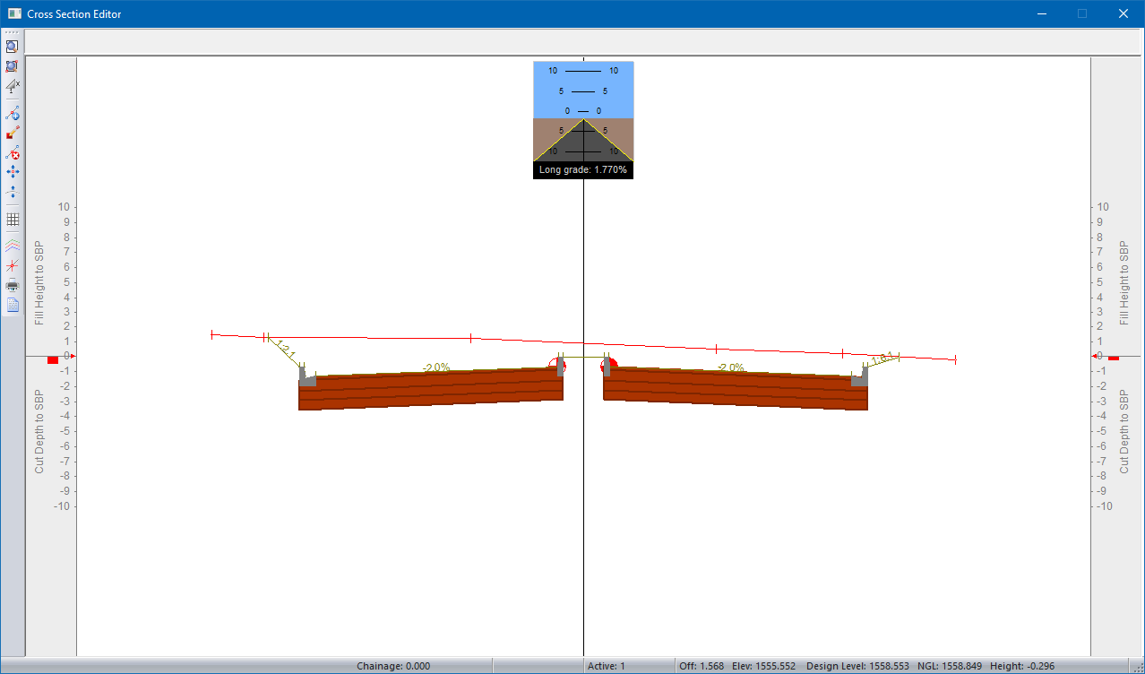
This function allows you to display the Cross Section Editor, where you can graphically edit each cross section. The advantages of graphical editing are the ability to edit several layers with reference to one another and that an instant visual verification of changes can be made.
Up to fifty cross sectional layers may be displayed per chainage. The layers and pen colours for the cross sections must be set up in the Section Lines option on the toolbar of the Cross Section Editor. Although several layers are displayed, editing may only take place on the current Active Line that is also selected in the Section Lines.
Specify the crossing services to display using the Section Lines.
Procedure
Cross Section edit: Indicate chainage or Esc to edit start chainage
Click on the plan of the active road to indicate the cross-section to be displayed.
The Cut/Fill Indicators, which are the grey sections on each side of the editor, indicate the height difference between the SBP and TOE point. These indicators make it easy to identify the areas where guardrails should be added.
These indicators do not display by default. To display them, select Section ► Graphical Edit. In the Groundline window, select the Cut/Fill Indicator checkbox.
Use the following keys to move through the chainages in the road database:
[PgDn] to move to the next chainage 'down' the road.
[PgUp] to move to the previous chainage 'up' the road.
[G] to Goto a specified chainage that must be entered.
The icons on the left side of the window provide quick links to useful functions. For example, click ![]() to access the Component Panel.
to access the Component Panel.