Civil Designer has two different functions for designing traffic circles:
The table below illustrates the differences between the two functions.
Mini-Circle
|
Roundabout |
Only three or four incoming legs. |
More than four incoming legs. |
Circular only. |
Can be non-circular. |
Configuration - A main road running through the mini-circle with one or two roads intersecting the main road. |
Configuration - Separate road for each leg and the circle. |
Models the mini-circle as two adjacent junctions. It “drapes” the circle onto the junctions and then grades the inner strings. |
Uses the Stockdale method for vertical design. |
Restrictive - Radii, lane width and crossfalls must be specified. |
Non-restrictive - use CAD work as input. |
Kerb lines are always circular and tangential to the circle. |
Kerb lines can have any shape. |
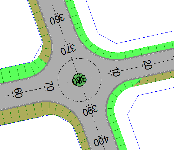
To add a mini-circle, you need a main road (running straight through the circle) and one or two intersecting roads that join up with the main road. A mini circle is in essence simply two adjacent junctions with specially calculated bell-mouth centre radii.
The centre point of the circle is placed on the centre line of the main road, half way between the junction points of the two intersecting roads.
The bell mouth radii are then calculated so the outside of the circle, with a radius of the centre circle radius + lane width. is tangential to the bell mouth arcs.
These bell mouths are graded using the normal junction S-curve method.
The outside circle, with a radius of the centre circle radius + lane width, is then draped over the two junctions and graded accordingly.
The centre circle and crown, if applicable, are graded using the specified crossfalls.
Lastly, the specified kerbs are added to the centre circle.
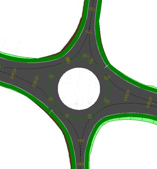
Vertical alignment design of roundabouts always presents challenges to the designer. R. Stockdale published a paper titled “The Vertical Alignment Design of Roundabouts” in August 1978, after which his method of vertical designing roundabouts became widely used. Civil Designer follows the Stockdale method.
The Stockdale method involves the following:
Indicate crown lines on the roundabout circle and on the approach roads, so that each of the approach road crown lines coincide with the circle crown. These points are called kiss-points.
Starting at one of the kiss-points, calculate the chainage of each kiss-point along the circle crown line.
Plot the start and end point at each approach crown line on a long section on the same chainage system.
Use these points and the known grades of the approach roads to do an S-curve smoothing for each approach crown line.
Height the circle crown line by fitting a spline through all the kiss-points.
You can edit the roundabout crown line, as well as the crown lines of any of the connecting roads.
You can also edit the width, crossfall and connecting grade of the roundabout circle.
Click Edit Junction.
You are prompted to:
Edit Junction: Indicate intersecting road, close to the junction
Click close to the Stockdale roundabout to be changed.
The Stockdale Roundabout Editor displays.
Use the normal string editing functions to alter the crown strings.
Click Close when you are complete.
You are prompted to:
Edit roundabout centre circle settings
The Roundabout Road Setup displays. The road name of the roundabout circle road displays in the Road Name edit box. The Destination Road Entity combo box and Road Name edit boxes are read-only.
You can now edit the Lane width, crossfall and tie-in slope.
Click OK when you are finished.
The Stockdale roundabout calculations are performed and the changes reflect.