Home > Storm Mode > Edit > Design Parameters
Edit the design parameters.
|
Icon |
Command |
Shortcut Key |
Toolbar |
|
|
STORMEDITDESIGNPARAMETERS |
|
|
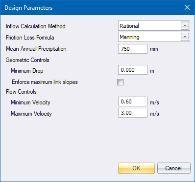
The Design Parameters allow you to select the inflow calculation method, and to establish guidelines for the design. These settings are read/saved as follows:
The defaults are normally read from the ProgramData directory when creating a new data file, unless the SetSharedFolder utility has been run to set a shared network resource. The SetSharedFolder utility is on the installation CD.
If no data set is open and the defaults are changed, the changes are saved in either the ProgramData directory or in the Shared Folder, if it has been set.
If a data set is open, the changes are stored with that data set.
Procedure
The Design Parameters display.

The following overall design parameters can be specified.
The Storm module supports four runoff calculation methods:
Rational
Wallingford Rational
Select from the required runoff calculation method. The selected option determines the input data required in the Edit Node data option.
The Storm module supports two friction loss formulae:
Select the required friction loss formula.
The geometric controls affect the placing of links relative to the natural ground line, and the calculation of node inverts.
Specify the minimum distance between the manhole invert level and the outlet level of an incoming culvert to apply a drop inlet in that manhole.
The flow controls set the hydraulic design parameters used in the calculation of link slopes and sizes.
Culverts are placed at a slope that maintains the minimum flow velocity specified here, or the maximum slope specified in the Link Tables, whichever is the least.
In practice, this results in the first (upstream) culverts being placed at the maximum link slope, typically 1 to 1.5%. Asthe link flows become significant down the line, the link slopes start flattening to the minimum slope specified in the Link Table.
This setting results in all links where the velocity exceeds the specified value being flagged in the results with the "**" symbol.