Home > Plan
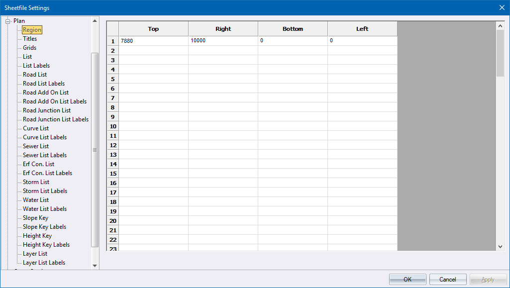
This section of the sheet file deals with the plan section of a sheet. The plan section can also include lists of road, sewer, storm and water data.

Before you can specify settings for the plan region, you need to define it by selecting Draw ► Regions ► Plan Region; or by entering values on the Region page. The plan region is defined as a sub-section of the global plotting region, and therefore its coordinates should not exceed those defined for the global plotting region.
You can position a plan plotting region anywhere on your plot sheet within the global plotting limits.
 Note that all
measurements entered in a sheet file are in 10ths of a millimetre, except
where specifically indicated. Text heights will be correct for the original
sheet file size but will change when the sheet file is scaled to fit other
paper sizes when generating a plot.
Option
|
Description |
Specify the area the plan must be plotted in. |
|
Specify the plan titles. |
|
Specify the parameters for the grid that will be drawn on the plan portion of the sheet file. |
|
The Layer List is a list of visible layers at the time the plot is generated, which can be included on the plan. |
|
Define the label configurations of the visible layer list using this page. |
The plan may include a list of coordinates. The coordinates are extracted out of the terrain database and you can apply a filter to extract only certain points. |
|
Define the label configurations of the coordinate list using this page. |
|
This section controls the drawing of a road horizontal alignment list on the plan. |
|
Define the label configurations for the Road List. |
|
This section control the details of the road's islands on the plan. |
|
This section controls the grid parameters in which the label parameters are placed. |
|
This section controls the details of the road's junction labels on the plan. |
|
This section controls the grid parameters in which the label information is placed. |
|
This section controls the detail of the road curve data on the plan. Note that the Curve listing routine will use the Language Settings, as specified in the Long Section - Lang tab. |
|
This section controls the detail of the road curve data labels on the plan. |
|
This page controls the drawing of a sewer schedule on the plan. |
|
Define the label options of the sewer schedule. |
|
This page controls the drawing of a sewer erf connection schedule on the plan. |
|
Define the label options of the erf connection schedule. |
|
This page controls the drawing of a stormwater manhole and culvert schedule on the plan. |
|
Define the label options of the stormwater manhole and culvert schedule. |
|
This page controls the drawing of a water pipe schedule on the plan. At bend points, the bend point chainage will be written into the Node Name column instead of the name of the previous node. |
|
Define the label options of the water pipe schedule. |
|
The plan may include a slope shading key. |
|
Define the label configurations of the slope shading key using this page. |
|
The plan may include a height shading key. |
|
Define the label configurations of the height shading key using this page. |
|
This page controls the drawing of a water valve schedule on the plan. |
|
Define the label options of the valve schedule. |
|
This page controls the drawing of a water hydrant schedule on the plan. |
|
Define the label options of the hydrant schedule. |
|
This page controls the drawing of a street tap schedule on the plan. |
|
Define the label options of the street tap schedule. |
|
This page controls the drawing of an air valve schedule on the plan. |
|
Define the label options of the air valve schedule. |
|
This page controls the drawing of a water connection schedule on the plan. |
|
Define the label options of the connection schedule. |