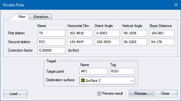
Home > Double Polar Dialog
|
Option
|
Description |
| Target | |
|
Target point |
Enter the name of the point to be created. |
|
Destination surface |
Select the surface on which the new point should be created. |
|
Load button |
Click to load the measurement details from the Observations & Figures data. The chosen observation data will be loaded into either First station or Second station depending on which had the focus when you clicked the button. |
|
Preview result |
Select this checkbox to have a preview of the calculation output displayed when you click Process. Only on accepting the preview will the calculation be adopted. |
|
Process Button |
Click to accept the current entries. |
|
Close Button |
Click to end the function. |
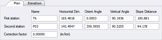
The Plan tab is for parts of the calculation relevant to the x-y coordinates.
|
Option
|
Description |
|
First and Second station - Name |
Enter the name of the point observed from. |
|
First and Second station - Horizontal Dirn. |
Enter the horizontal direction from the station to the target point. |
|
First and Second station - Orient Angle |
Enter the orientation angle that is to be applied to the observed direction at the station. Leave as 0.0000 for no orientation. |
|
First and Second station - Vertical Angle |
Enter the vertical angle between the station and the target point. If the measured distance is the horizontal distance then the vertical angle should be set to 90.0000, otherwise it is assumed that the measured distance is a slope distance and the entered vertical angle will be used to reduce the slope distance to the horizontal. |
|
First and Second station - Slope Distance |
Enter the measured slope or horizontal distance from the station to the target point. |
|
Correction factor |
Enter the correction to be applied to the measured distances in meters per kilometre. |
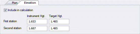
The Elevation tab is for parts of the calculation relevant to the z target coordinates.
|
Option
|
Description |
| Include in calculation |
Select this checkbox for the elevation of the target point to be calculated by averaging the height difference from both the first and second station. The vertical angle and slope distance is used with the instrument height and target height. The “curvature and refraction” correction is applied. The output will have no z-coordinate information if this option is not selected. |
| Instrument Hgt | Enter the instrument height of the first and second station. |
| Target Hgt | Enter the target height of the first and second station. |
See Also Double Polar