Home > Roads Mode > Alignment > Check Sight Distance
Check minimum sight distances.
Icon |
Command |
Shortcut Key |
Toolbar |
|
RD_CHECKSIGHTDISTANCE |
|
|
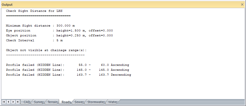
This function allows you to calculate the areas along the road alignment where the driver cannot see the specified object, over a specified minimum sight distance. These areas are marked in the specified pen colour, on either the Vertical or Horizontal alignment.
For this function to work correctly, the road design process must be completed and a final design road layer must exist. The program does sight distance checking in both horizontal and vertical planes automatically.
The program uses the batter cross-sections for sight checking. If the offset of the toe points is less than the specified road reserve, the program includes ground points beyond the toe point and up to the road reserve width, when doing sight distance checking.
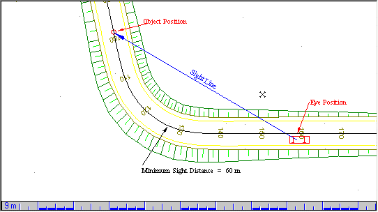
The distance from the driver to the object is always measured along the horizontal alignment, while the sight line from the driver to the object (blue line) is taken as a straight line. If this line crosses the toe point or the road reserve, whichever has the greater offset from the centre line, the program registers a horizontal failure.
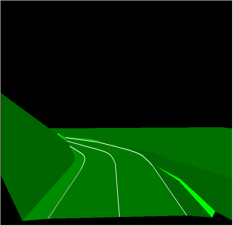
Vertical sight failure occurs if a driver is unable to see the object over the minimum sight distance because of a vertical curve, or when cut banks restrict his vision as illustrated by the figure below.
Procedure

Fill in the relative information and click OK.