Icon
Command
Shortcut Key
Toolbar
![]()
PLOTGENERATE
Misc
Generate a plan on a separate layout.
Icon |
Command |
Shortcut Key |
Toolbar |
|
PLOTGENERATE |
|
Misc |
This function allows you to generate a plan in a separate layout window suitable for printing or saving.
Procedure

Click ... and select the Plan.sht sheet file from the C:\Users\Public\Documents\Knowledge Base Software\Sheetfiles directory, as shown below.


The Plan Setup page displays. Here you can define one or more sheets, the scale, grid settings and key plan options.

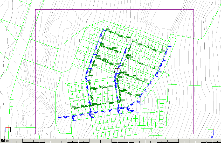
Click Add to define the position of a plot sheet. The Plan Setup window is removed and a rectangle representing the useable area in the sheetfile displays on your drawing.
Plan Plotting: Indicate plot centre (Right-click to end)


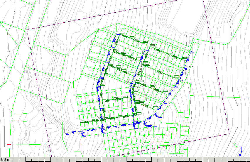
Plan Plotting: Indicate rotation


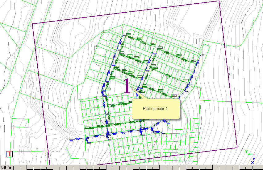
You can now edit any of these values, add additional plots, move existing plots, change the Grid Settings, and even define a Key Plan. In this example, you are going to click Next to create the layout.

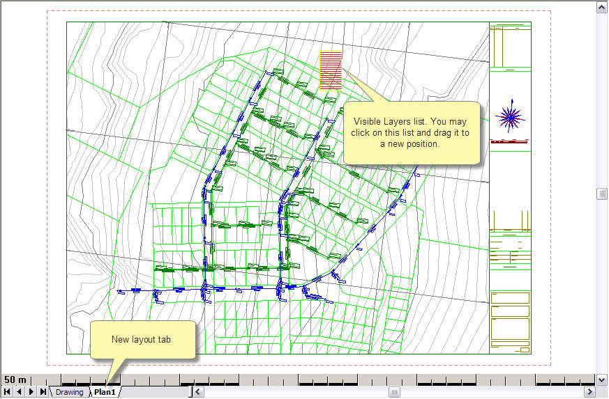
Click Finish to generate the plan layout.

Here you can edit all the custom text in one place. The Field column contains the custom text and the Text column contains a replica of it which can be edited.
If Apply to all layouts is not selected and there are multiple layouts in the plot set, clicking OK will cause it to appear again with the edit values of the previous layout. You can now change it per plot. Alternatively, you can select Apply to all layouts, which will apply it to all the layouts in the plot set and the dialog will not pop up again during the plot set.
 Note that
this dialog will not appear during a Force Dynamic Plot.
