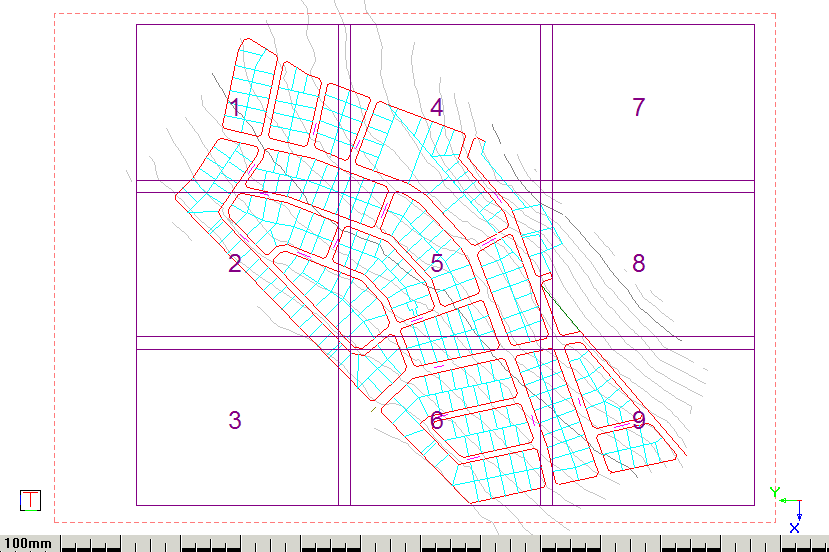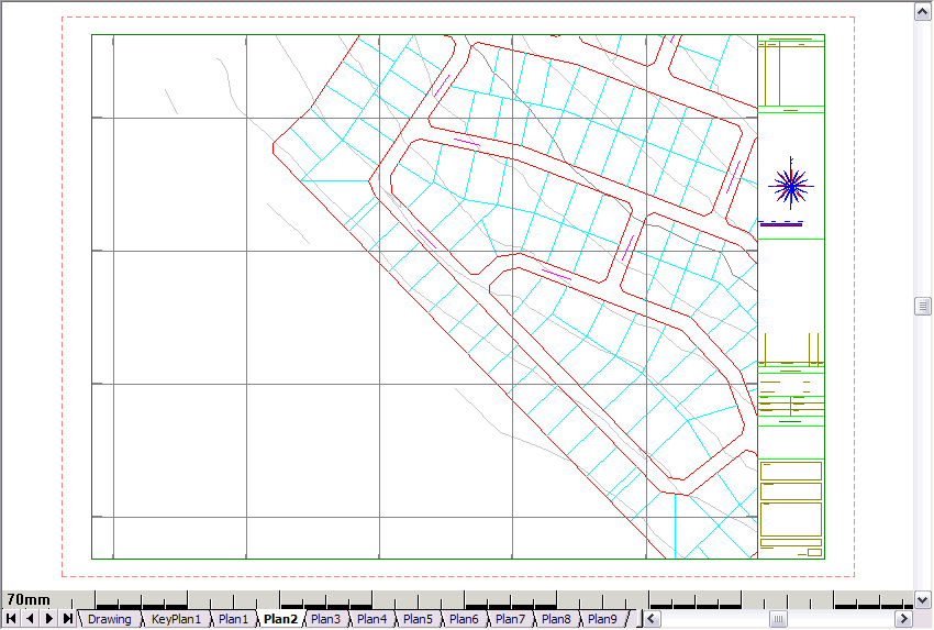
This function allows you to define a Key Plan, which shows the position and numbering of a series of plans.
Before you generate the key plan, you should have defined one or more plot sheets. The Key Plan option then allow you to position a master sheet over the plot sheets to show their position relative to the overall site and each other.
Procedure
In this example you first define a number of plot sheets using the Auto Define option.

Select the Plan.sht sheet file from the standard sheet files supplied with Civil Designer, and then click Next.


The Plan Setup window is removed and your drawing displays.

Specify a distance of 20m and click
Enter  .
.
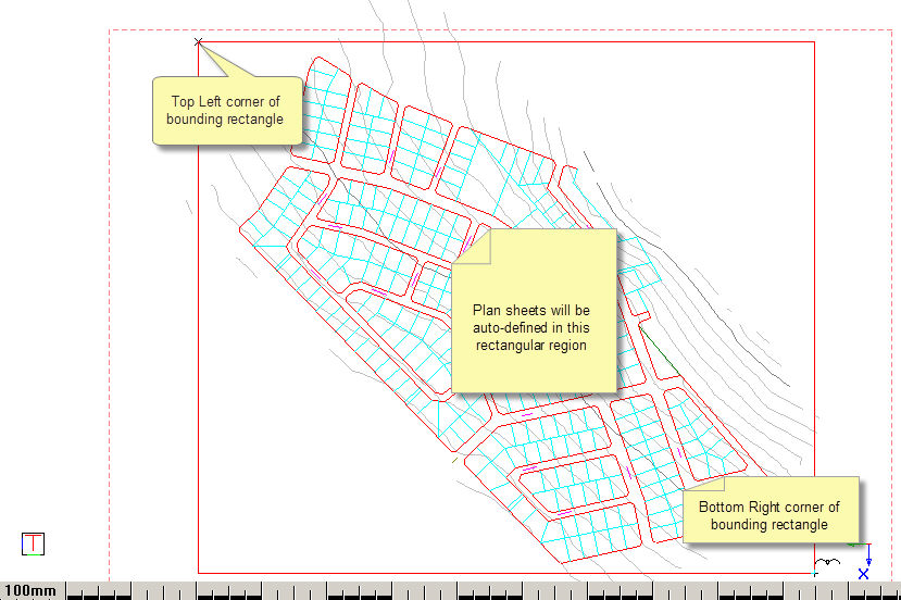
Indicate the start point of the defining rectangle
Position the cursor at the top left corner of your area of interest and click.
Indicate the end point of the defining rectangle


Set up your parameters and click OK.
Plan Plotting: Indicate plot centre (Right-click to end)
Position the rectangle around the defined sheets and click. You can rotate the key plan sheet if required.


Select which lists you want to include on your drawing and click Finish.
If there is Custom Global or Plan Text in the brackets (<>), the Custom Strings for Plan and Global Titles dialog displays.

Here you can edit all the custom text in one place. The Field column contains the custom text and the Text column contains a replica of it which can be edited.
If Apply to all layouts is not selected and there are multiple layouts in the plot set, clicking OK will cause it to appear again with the edit values of the previous layout. You can now change it per plot. Alternatively, you can select Apply to all layouts, which will apply it to all the layouts in the plot set and the dialog will not pop up again during the plot set.
 Note that
this dialog will not appear during a Force Dynamic Plot.
