Home > Water Mode > Data > Reservoirs
Display reservoir data.
|
Icon |
Command |
Shortcut Key |
Toolbar |
|
|
WATERDATARESERVOIRS |
|
|
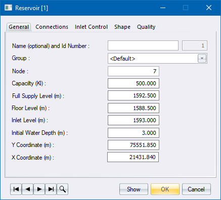
Reservoirs are defined by name, Id ,and node on which they are located.
There is no limit to the capacity of a reservoir. Dams can be modelled by entering large capacity values.
Procedure
The reservoir window displays with five tabs.

|
Option
|
Description |
|
Name & Id |
Name is optional. The Water module automatically assigns an Id. |
|
Group |
Refers to a group that the element belongs to. New elements initially belong to a group that was selected as a current group at the time the element was created. Group creation and manipulation is explained in the chapter on groups. |
|
Node |
This is the node number on which the reservoir is situated. |
|
Capacity (Kl) |
The total storage capacity of the reservoir given in kilolitres. |
|
Full supply level (m) |
Elevation of the full supply level. |
|
Floor level (m) |
Elevation of the reservoir floor level. |
|
Inlet level (m) |
Elevation of the inlet. |
|
Water depth (m) |
Water depth inside the reservoir at the start of the analysis, measured from the floor of the reservoir. |
|
Y / X Coordinates (m) |
Coordinates are automatically picked up from the node that the reservoir is positioned on. |
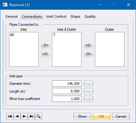
There are three entry areas in the reservoir Connections table, namely:
Inlet
Inlet and Outlet
When you first enter this menu, all the pipes are listed in the middle area. To define the function of a pipe, highlight the pipe in the middle and press the arrow in the required direction; or drag the pipe to the desired area - either inlet or outlet only.
Pipe numbers are automatically sorted into ascending order so it is not necessary to drag pipe numbers across in sequence. Multiple pipes cannot be selected and dragged across in one movement.
|
Pipes connected to... |
Description
|
|
Inlet |
If the pipe is described as an inlet only, only flow into the reservoir is possible. The pipe automatically functions as if a check valve has been assigned to this pipe. An inlet control valve can also be applied to the inlet pipe, as per the options in the bottom of the screen. If an inlet control valve is chosen, the water depth for the open and closed position of the valve must be defined. |
|
Outlet |
If the pipe is described as an outlet only, only flow out of the reservoir is possible. |
|
Inlet and Outlet |
Flow in both directions is possible. |
|
Option
|
Description |
|
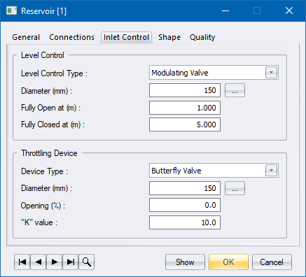
Level Control |
|
|
Level Control Type |
Specify the level control type. The options are:
|
|
Diameter (mm) |
Specify the diameter of the valve in mm. Defaults to the diameter of the inlet pipe are set to 0. |
|
Fully Open at (m) |
Specify at what water level above the reservoir floor the valve is fully open. |
|
Fully Closed at (m) |
Specify at what water level above the reservoir floor the valve is fully closed. |
|
Throttling Device |
|
|
Device Type |
Specify the type of throttling device. The options are:
|
|
Diameter (mm) |
Specify the diameter of the throttling valve in mm. |
|
Opening (%) |
Specify the % opening on the throttling valve. |
|
"K" value |
Specify the minor loss coefficient of the valve. |
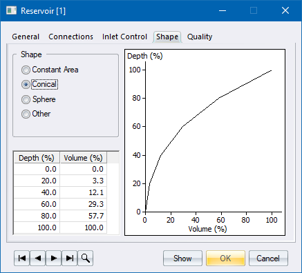
The shape of the reservoir affects the actual depth of the water at a given point in time during a time simulation, and therefore affects the pressure. You can define any shape of reservoir by selecting one of the most common shapes. Alternatively, select the Other option and define the water depth versus volume.
|
Option
|
Description |
|
Shape |
Select the reservoir shape. The options are:
You must specify the depth-volume curve for the Other shape option. |
|
Depth/Volume table |
Specify the depth-volume curve in percentages. |
|
Depth/Volume graph |
The graph is updated as you type values into the table. |
|
Option
|
Description |
|
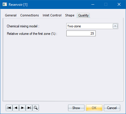
Chemical mixing model |
Select one of the following: |
|
Complete |
Default mode that assumes that chemicals entering the reservoir instantaneously mix with the entire volume of already present water. |
|
Two-zone |
Used when there is only one combined inlet/outlet pipe, or the inlet and outlet are close to each other without any partition walls. The assumption is that instantaneous mixing happens only in the zone close to the inlet/outlet. Transfer between zones depends on the net inflow to the first zone. |
|
First in first out |
The assumption is that partition walls direct water from the inlet towards the outlet, without any mixing taking place in the process. |
|
First in last out |
Mixing does not happen at all, but the inlet is close to the outlet (or combined) without any partition walls. |
|
Relative volume of the first zone (%) |
Used only in conjunction with the two-zone mixing model. |