Home > Water Mode > Data > Nodes
Display node data.
Icon |
Command |
Shortcut Key |
Toolbar |
|
WATERDATANODES |
|
|
Nodes in the network are defined by Id number, elevation, demand type, coordinates and name. A node is defined at the start and end of each pipe. It is not necessary to define new nodes at each change of direction, as multiple bends can be accommodated between nodes.
Nodes are necessary at pipe connections. For example, where:
Three or more pipes join.
There is a change of diameter.
There are demand points.
It is not necessary to define a node at pump stations and valves, as these are defined by the pipe Id number on which they are situated.
All nodes in the model must be assigned an elevation in order to be able to determine the hydraulic grade line and residual head at each node.
The elevation is defined in metres above some chosen datum level. Demands are optional.
Procedure
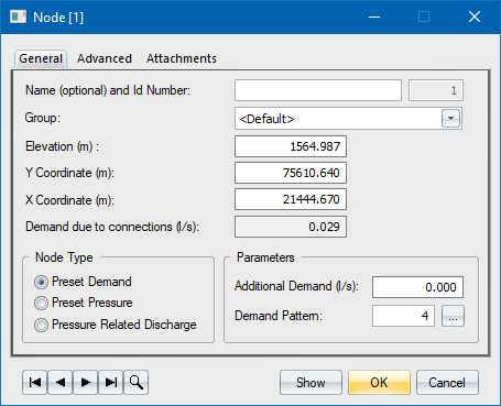
The Node data window displays.

Option
|
Description |
Name |
Specify an optional name for this node. |
Group |
Refers to a group that the element belongs to. New elements initially belong to a group that was selected as a current group at the time the element was created. Group creation and manipulation is explained in the chapter on groups. |
Elevation |
The elevation of the node. |
Y Coordinate |
The Y coordinate of the node. |
X Coordinate |
The X coordinate of the node. |
Demand due to erf connections |
Demand due to connections is automatically calculated by the software when the user adds or removes connections or when the connection parameters have changed. |
Node Type |
|
Preset Demand |
Additional demand is applied on top of the demand due to erf connections or due to street taps. It should be kept on zero when using erf connections or street taps, unless it is due to some external cause, such as industrial or commercial usage.
Demand is given in litres per second, and equals the average daily outflow. The water demand at any moment in time is obtained by multiplying that average node outflow by the corresponding hourly water use coefficient i.e. the Demand pattern coefficient. The flow value can be negative, which designates inflow. The Demand Pattern can be typed in, or selected from the file by clicking .... |
Preset Pressure |
Where portion of a network is being analysed, preset pressure nodes are required for simulating the inflow from the rest of the network.
This type of node would typically be used where a network is fed from a main supply pipe, another network, or a fixed head borehole or dam outlet. In this case, the known pressure is applied to the node to simulate the effect of the source. The preset pressure can be constant or variable. If variable, click Settings and type in a value each 15 minutes for a 24 hour period. |
Pressure Related Discharge |
This is an outlet for which the outflow value depends on the current pressure in the corresponding node in the network.
Nodes of this type are usually used for aerators in water treatment plants, and in calculations involving accidents and pipe bursts. The only input detail required here is discharge at one bar, which is given in litres per second. |

Water demand is the anticipated amount of water that consumers would use, calculated according to a prescribed per capita allowance or historical figures for a certain region. Water consumption is actual draw-off at points of connection, as observed on water meters.
In ideal conditions, when the supply is sufficient and pressures in the network do not vary too much, consumption should be equal to demand, and each consumer would use exactly the amount of water that was allocated to him. That is the classical approach to modelling, implemented in most software packages.
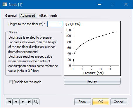
In real world networks, consumption is not equal to demand. Consumption varies with the pressure, especially in cases of restricted water supply or when pressure differences are significant. In such instances, it is entirely possible that consumers in high pressure parts of the network use way more than average, while at the same time low-pressure parts of the network suffer shortages.
The analysis uses the Advanced parameters in the Water Specific Settings.
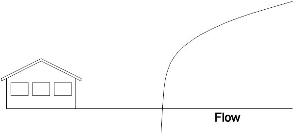
For a single consumer, draw-off is linked to available pressure by an exponential equation:

Where:
Q = Actual consumption
Q0 = Water demand
P = Available pressure
P0 = Reference pressure
E = Exponent
Reference pressure is the pressure at which consumption would be exactly the same as predicted by demand calculations. The typical value is around three bar.
Equation 1 is therefore fully applicable, without any corrections, for single storey buildings.

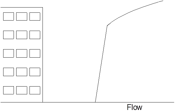
For multi-storey buildings the situation is a bit more difficult, as it is possible that the free water level lies somewhere between the ground and top levels. Theoretically, one can apply equation 1 to each floor separately, taking into account pressure differences caused by the floor height. The result, which also complies with field measurements, would be an almost straight line from ground level to the height of the top floor, and an exponential relation, as in equation 1.
