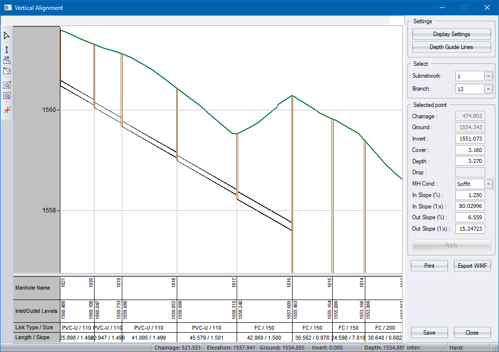

This Vertical Alignment Editor displays the long section of selected culverts.
The ground line(s) are extracted from the DTM model according to the surfaces specified in the DTM Surfaces.
|
Option
|
Description |
||||||||||||||
|
Display Settings |
Choose from the following options to display in the long section detail area:
|
||||||||||||||
|
Depth Guide Lines |
Set the minimum and maximum cover guideline display. |
||||||||||||||
|
Select |
Select the Subnetwork and branch number of the branch that you want to view. |
||||||||||||||
|
Toolbar |
The toolbar buttons access the following functions:
|
||||||||||||||
|
Information Bar |
The data will be updated as the cursor moves in the longitudinal section view. The following information will be displayed - Chainage, Elevation, Ground Level, Invert Level, Depth and Intermediate and Hard levels if these surfaces has been activated in the DTM Surface Dialog. |
||||||||||||||
|
Selected point |
Here you can edit the invert level, cover level, manhole depth, specify a fixed drop, or set the incoming or outgoing slopes for the selected manhole. |
||||||||||||||
|
Print button |
Print the current longsection view. |
||||||||||||||
|
Export WMF |
Export the current longsection view to a Windows Meta File. |
||||||||||||||
|
Save button |
Save the changes made to the long section. |
||||||||||||||
|
Close button |
Click to end the function. |