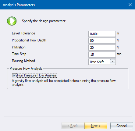

Specify the parameters for the Unit Inflow Hydrograph analysis.
|
Option
|
Description |
|
Level Tolerance |
Determines the tolerance that will be allowed when comparing the incoming and outgoing link levels in each node. Sometimes when you are evaluating an existing network with the links at fixed slopes, the rounding off of the slopes will result in an incoming pipe which is, say 2mm, lower than the outgoing link which has been given a fixed inlet level. Normally Civil Designer will display an error message and then adjust the inlet level of the outgoing link to be lower then the incoming link. This setting prevents the level adjustment if the difference is within the tolerance. |
|
Proportional Flow Depth |
Determines the maximum flow depth that will be allowed in the links. Usually this will be set to 80%. |
|
Infiltration |
Defines the percentage extra inflow due to stormwater infiltration. The calculated inflows are increased by this factor. |
|
Time Step |
Defines the time increments used in the routing and analysis of flows. |
|
Routing Method |
Determines the routing method. There are currently two options - Continuity and Time Shift. |
|
Run Pressure Flow Analysis |
Select this checkcbox to run a pressure flow analysis on the network after the initial steady state analysis. Only available for the Inflow Hydrograph method. |
|
Next button |
Click to display the next page. |
|
Cancel button |
Click to cancel the function. |
See Also Network Analysis