Icon
Command
Shortcut Key
Toolbar
![]()
HATCH
Drawing
Create hatches or solid-fill using the circle, rectangular, polygonal, entity, intersection or track draw boundary method.
Icon |
Command |
Shortcut Key |
Toolbar |
|
HATCH |
|
Drawing |
This function allows you to insert a hatch pattern or solid fill elements of the drawing, by specifying the hatch/fill parameters and indicating the perimeter.
You can define the hatch perimeter in a number of ways:
Auto-tracking of the perimeter.
Defining entities.
Indicating entities and their intersections with other entities.
You can also change a hatch by selecting it and the dragging the hatch nodes to new positions. The hatch entity can have one of four fill types:
The Pattern hatch types also allow you to specify the pattern origin in order to make the pattern symmetrical to the hatch area or to retain the integrity of complicated patterns.
Procedure

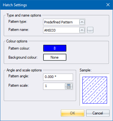
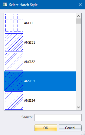
Select the pattern and click OK. The pattern is displayed in the Sample section.
Click OK to continue; or Cancel to exit the settings.

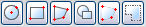
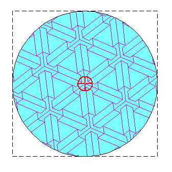
To define hatch boundaries as circles:
Click the icon ![]() .
.
You are prompted to:
Boundary 1 - Indicate centre point of circle
Use the snap or jump modes to move to the centre of the circle, and then press [Enter] or click. A highlighted circle rubberbands.
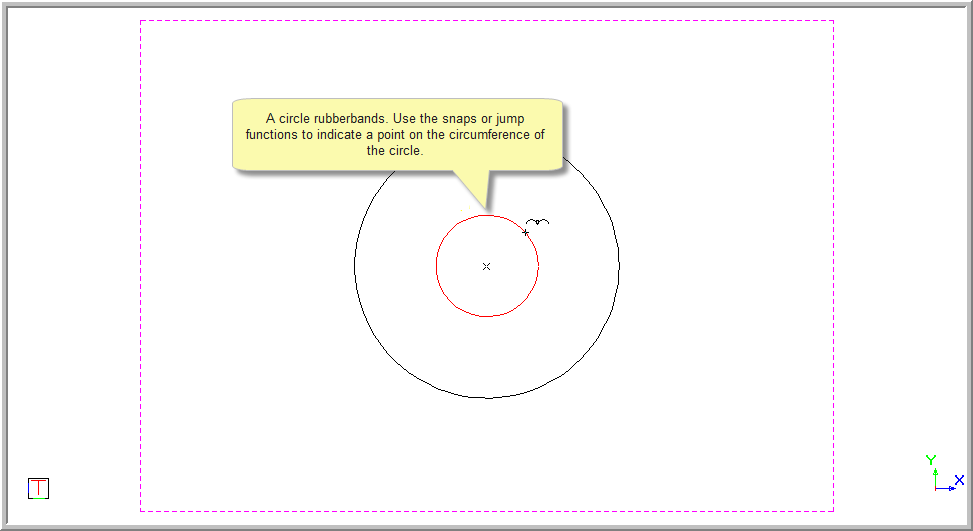
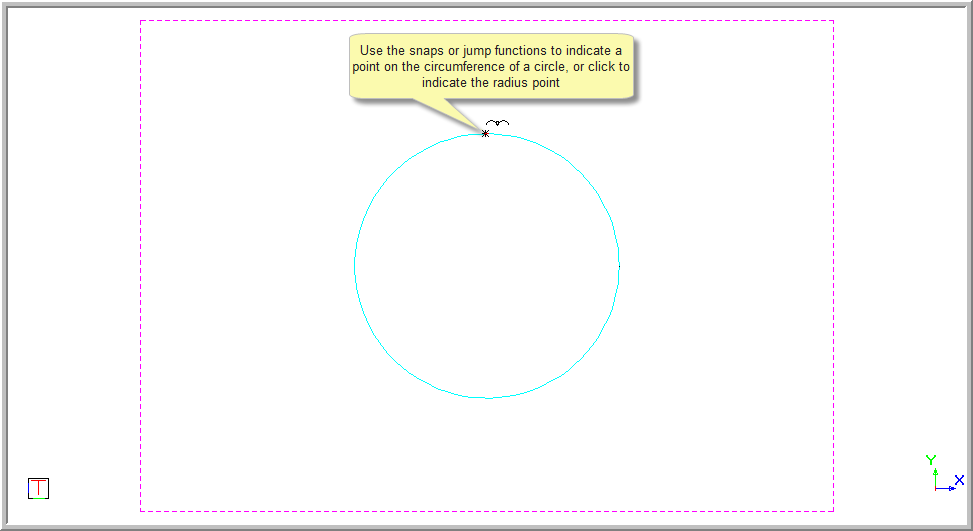
Boundary 1 - Indicate point on radius

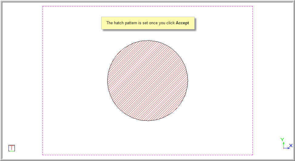
If you do not select Accept, the hatch pattern is not set.
To hatch a rectangular entity:
Click the Hatch Rectangle icon
![]() .
.
You are prompted to:

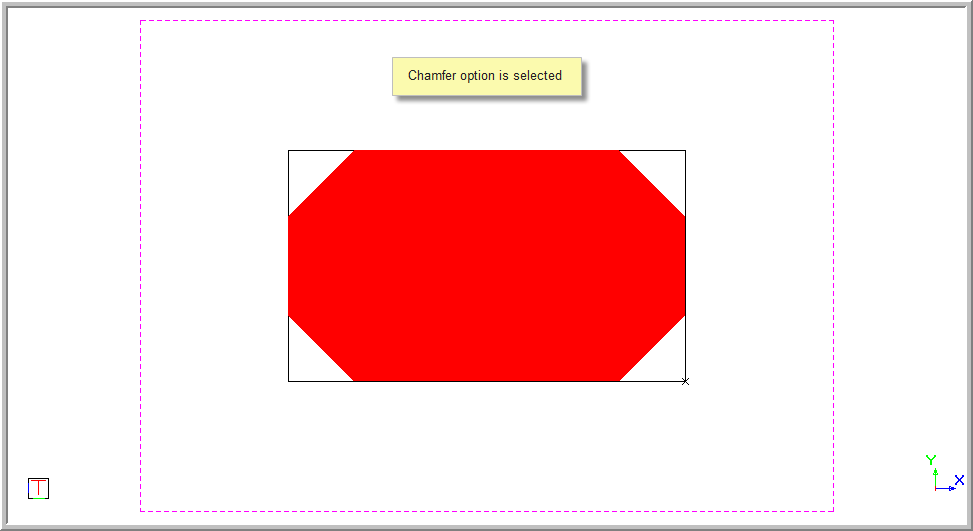
Select the type of Finish you want from the dropdown list.

If you select a Chamfer or Fillet finish, you can enter a value in the text box.

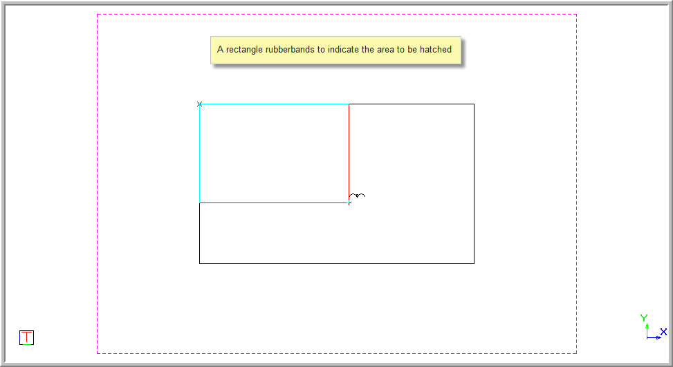
You are prompted to:

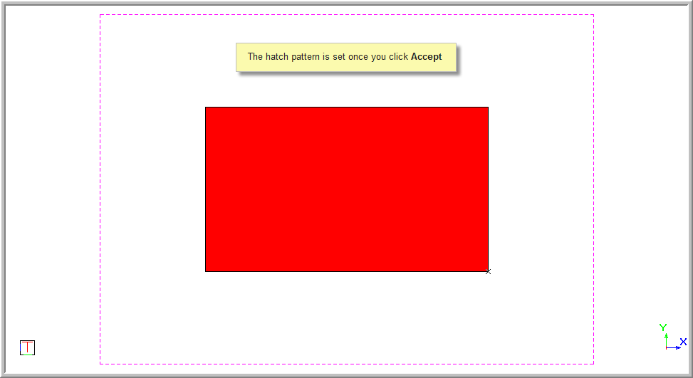
Use the snap or jump modes to move to the second point of the rectangle and click to indicate the position. The rectangle is hatched.

If you do not click Accept, the hatch pattern will not be set.

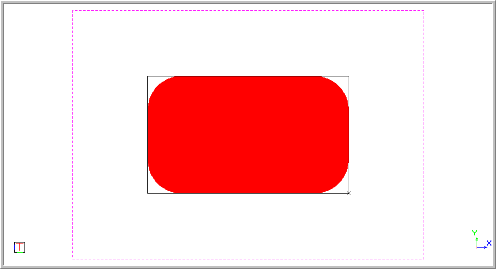
The rectangle below is hatched with a chamfer of 40.
The rectangle below is hatched with a fillet of 40.
To hatch straight line entities using a polyline selection:
Click
the Hatch Polyline icon ![]() .
.
You are prompted to:
Boundary 1 - Click on start position of hatch polyline (Right-click for menu)
Use the snap or jump modes to move to the first point, and then click or press [Enter] to indicate the position.
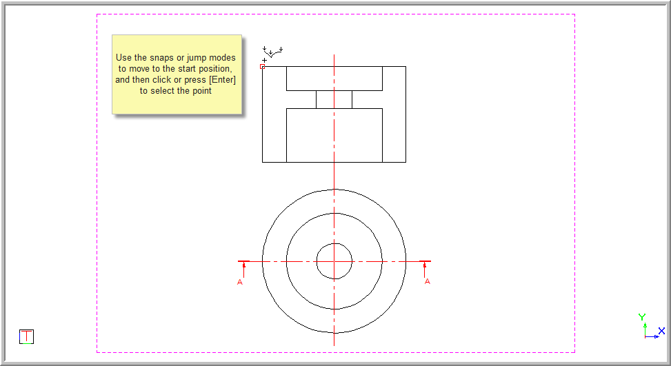
A line rubberbands.
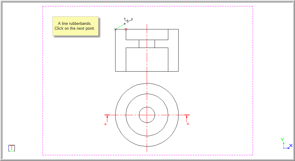
You are prompted to:
Boundary 1 - Click on next position of hatch polyline (Right-click for menu)
Move to the next point using the snap or jump modes, and then click or press [Enter].
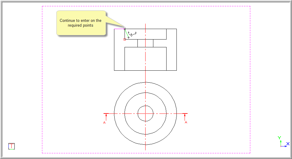
Continue to enter on the point around the entity to be hatched.
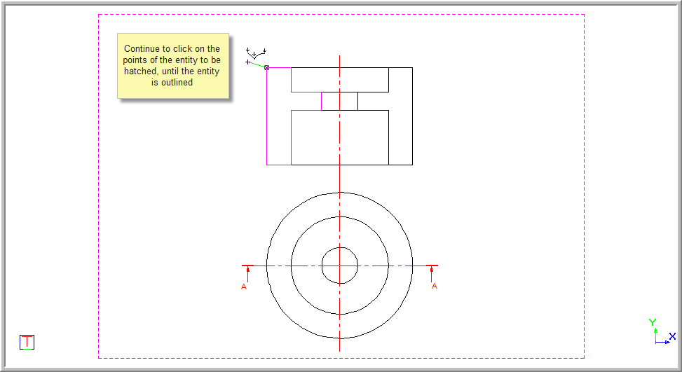
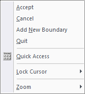
Once the entity is outlined, right-click to open the context menu.
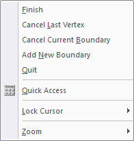
Select Cancel Last Vertex to undo the last selection.
Select Cancel Current Boundary to remove the entire selection and start again.
If you select Add New Boundary, you are prompted to:
Boundary 2 - Click on start position of hatch polyline (Right-click for menu)
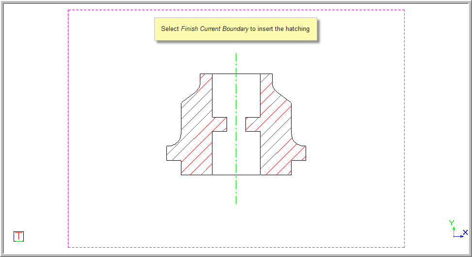
The Close Current Boundary option joins the last entered point to the start point, and completes the polyline hatch function.
The hatching is inserted.
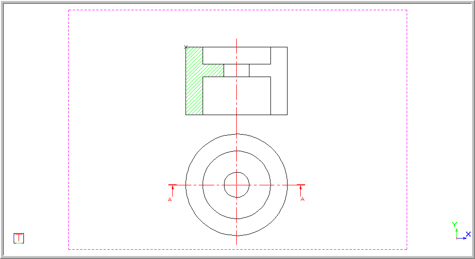
The function repeats and you are prompted to:
Boundary 2 - Click on start position of hatch polyline (Right-click for menu)
You can outline a new boundary to hatch.
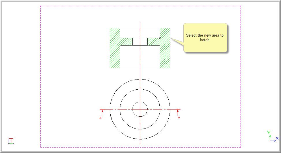
Once you have completed selecting the areas to hatch, right-click and select the Accept option.

To hatch by selecting entities:
Click
the Hatch Entity icon ![]() .
.
You are prompted to:
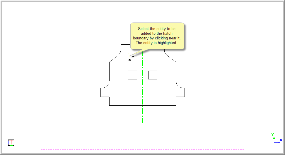
Boundary 1 - Indicate entity to add
Click near the entity to be added. The entity is highlighted, indicating it has been selected.
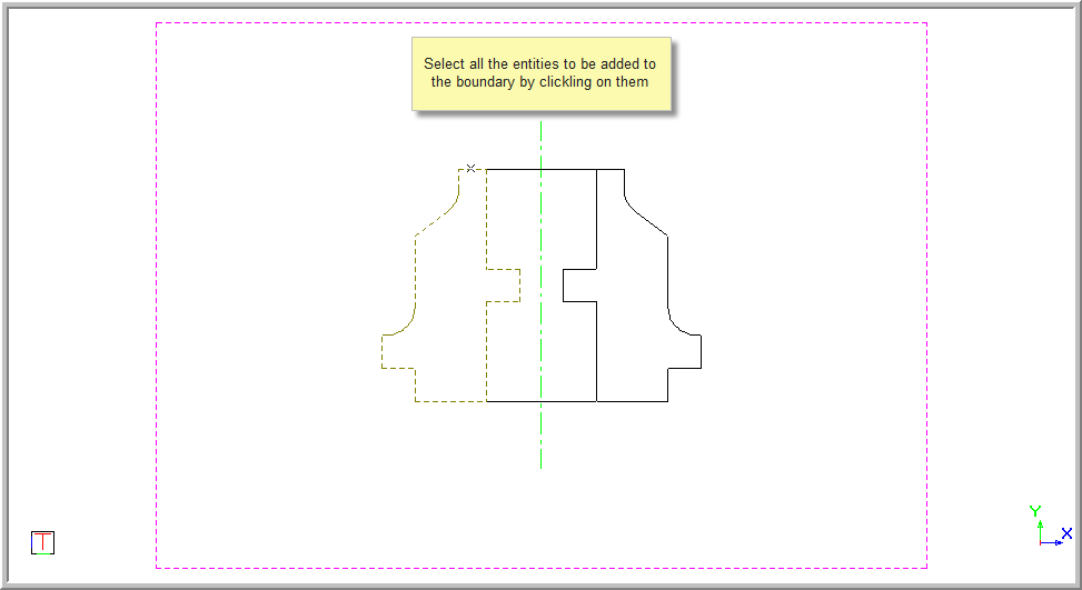
You are prompted to:
Boundary 1 - Indicate entity to add
Continue to select the entities to be added to the boundary.
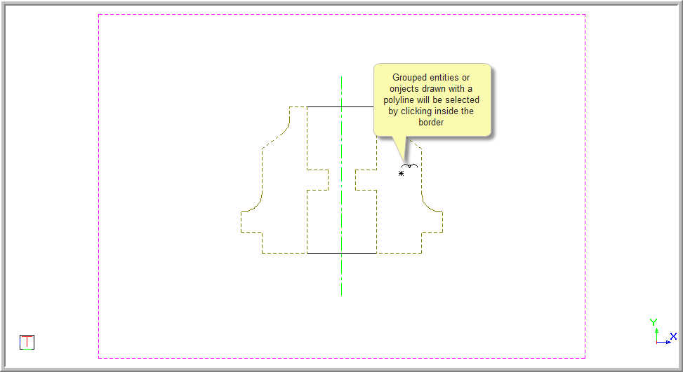
If the entities have been grouped or the entity is a drawn with a polyline, the object can be selected by clicking inside the border.
The right side of the lock below has been grouped and is selected by clicking inside the border.
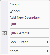
Once all the entities have been selected, right-click and select an option from the popup menu.
Select Add New Boundary to select a new hatch boundary method.
To hatch an entity by intersections:
Click
the Hatch Intersection icon ![]() .
.
You are prompted to:
Boundary 1 - Indicate first boundary element (right-click for menu)
Click the first element.
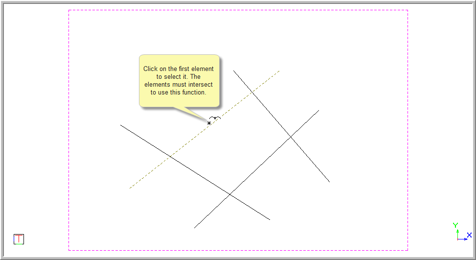
The element is highlighted to indicate it has been selected.
You are prompted to:
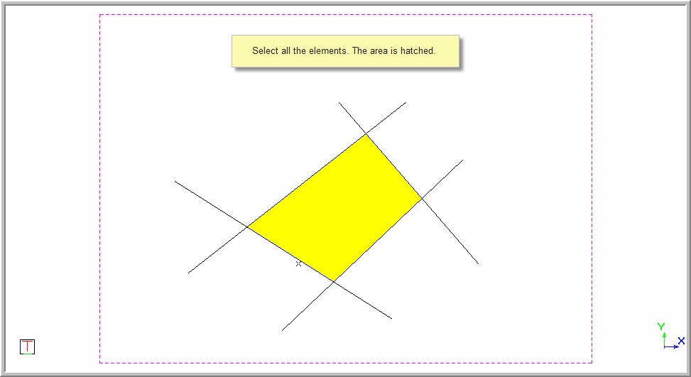
Boundary 1 - Indicate next boundary element (right-click for menu)
Continue to click on the elements. You need to select the elements in an order where the next element selected intersects with the last element selected. If you don't, a warning informs you that the indicated entities do not intersect.
Once the last intersecting element is selected, the area is hatched.
The function repeats and you are prompted to:
Boundary 2 - Indicate first boundary element (right-click for menu)
You can now select the next boundary using the intersection option if required.
When you are finished selecting entities to be hatched, right-click and select Accept to set the hatching, or Add New Boundary to add a new boundary using the same or a different method.


To hatch an entity by tracking:
Click
the Automatic Tracking icon ![]() .
.
You are prompted to:

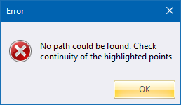
The area selected must be a closed boundary for this option to work.
If the area is not closed, an error message is displayed.
Click inside the perimeter of the area to be hatched and near an entity.
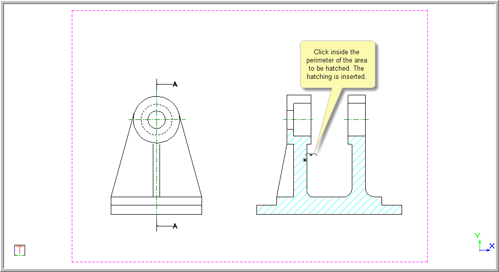
The area is hatched and the function repeats.
You are prompted to:

Continue to click inside the areas to be hatched.
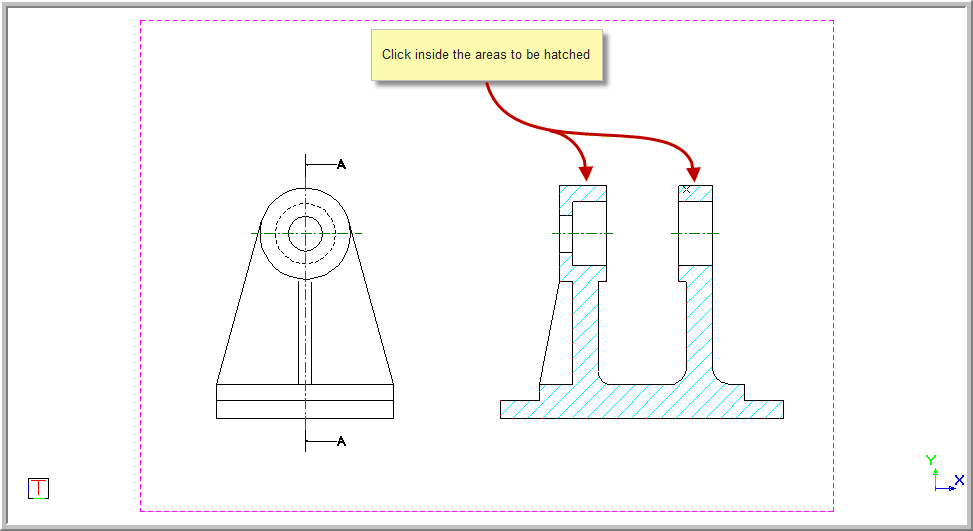
Right-click once you have finished selecting the boundaries to open the context menu.
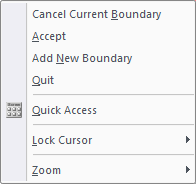
If you have made a mistake in your selection, select Cancel Current Boundary and all selections will be undone.
Select Accept to complete this phase of adding hatch.
You are again prompted to:


To hatch an island (exclude from hatching) entity, you can select the Detect Islands option.

 This option is
limited to ten islands. If more are required, hatching will have to be
done manually for each island followed by the enclosing boundary.
This option is
limited to ten islands. If more are required, hatching will have to be
done manually for each island followed by the enclosing boundary.
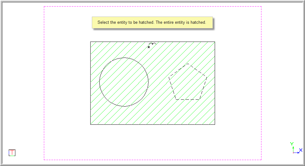
The Detect Islands checkbox allows you to place the cursor near the perimeter of the entity to be hatched and click.
The selected entity is hatched and the entities which fall inside the hatch area are excluded.
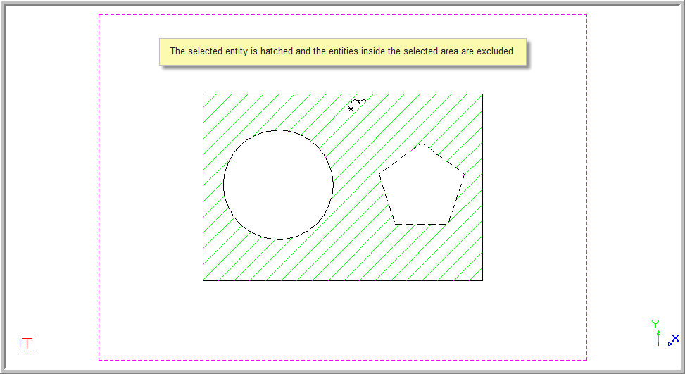
The Track Selection checkbox allows you to select the area to be hatched and then select the entities to be excluded from the hatching.

Click inside the entities to be excluded from the hatching.
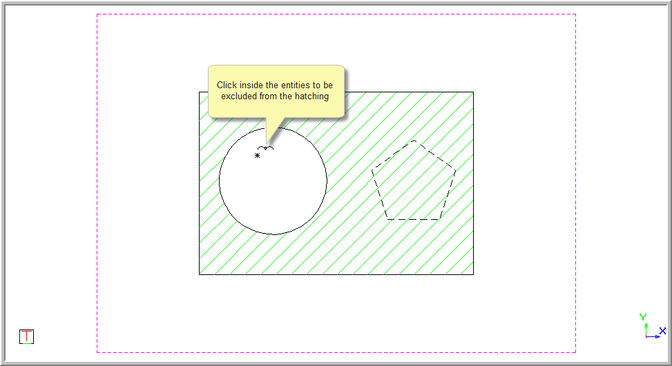
The hatching is removed from the selected entities.
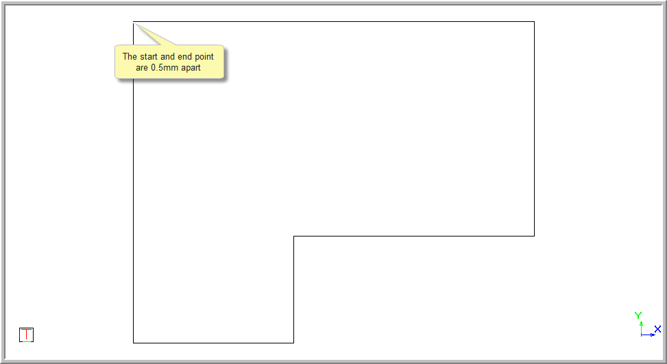
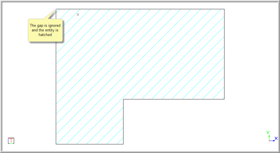
The Tolerance option allows you to specify a distance to be ignored when the entity is not closed.
This allows the auto tracking to still track around the selected entities even though they are not closed.

The example below shows the a shape that is not closed.
The gap between the start and end points is 0.5mm.
With the tolerance set to 0.001 you will receive the following error message.

If the tolerance has been set to 1, any gap less than the tolerance value will be ignored and the entity will be selected and hatched.
The number which appears after the word Boundary in the prompts refers to the next boundary to be selected.
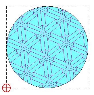
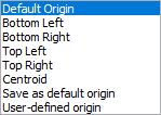
The Pattern Origin dropdown list includes the following options:
Option
|
Description |
Default Origin |
This is a 2D point on the hatch plane specifying default pattern origin. It is a global system variable i.e. across drawings. If no pattern origin is specified the default origin is used. If no default origin is specified the zero point on the hatch plane (0,0) is used as the default pattern origin. |
Bottom Left |
This is a 2D point at the bottom left of the hatch extents rectangle.
|
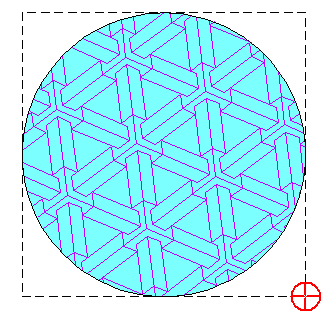
Bottom Right |
This is a 2D point at the bottom right of the hatch extents rectangle.
|
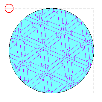
Top Left |
This is a 2D point at the top left of the hatch extents rectangle.
|
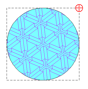
Top Right |
This is a 2D point at the top right of the hatch extents rectangle.
|
Centroid |
This is a 2D point at the centroid/barycentre of the hatch extents rectangle.
|
User-defined origin |
This is a 2D point user-defined point not related in any way to the hatch extents rectangle. The user-defined point button must still be clicked for the pattern origin to be specified. |
Save as default origin |
This option updates the default pattern origin with current pattern origin. |
Select a predefined or user pattern type hatch, and then press [F4] to open the Properties Bar.
.png)
Click Pick Origin.
You are prompted to:
Indicate the pattern origin
Click anywhere in the drawing to set the pattern origin at the indicated point.
The boundary extent
options (bottom-left, bottom-right, top-left, top-right and centroid)
will no longer be available for the Pick
Origin button. This is easily remedied by ensuring that the
Show selection handles option
is checked in the General tab of System Settings, and the snap to point
option is enabled when indicating the pattern origin.