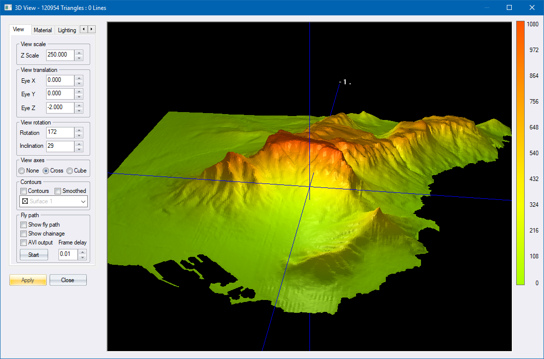
Some of the settings made on the tabs are applied to the view immediately. Other settings need to be entered. When you click Apply, the view is redrawn according to the new settings.
|
Option
|
Description |
|
View Scale |
|
|
Z Scale |
Enter the scaling exaggeration factor to be applied to point heights. |
|
View Translation |
|
|
Eye X, Eye Y and Eye Z |
Enter the ordinates of the view position. Alternatively, right-click and drag the mouse pointer in the view to change the Eye X and Eye Y values interactively. |
|
View Rotation |
|
|
Rotation and Inclination |
Enter the rotation and inclination angles of the view. Alternatively, click and drag the mouse pointer in the view to change the Rotation and Inclination interactively. |
|
View Axes |
|
|
None, Cross or Cube |
Select these options to turn off all axis display, to display the axes as a 3D cross, or to display the axes as a unit 3D cube respectively. |
|
Contours |
These are disabled if there are no generated contours available. Select this checkbox to display previously generated contours and select from the dropdown list the generated contours that are available. The interval of the displayed contours are what you specified when you generated them. |
|
Fly path |
These are disabled if you have not performed the Fly path routine. |
|
Show fly path/ |
Select the Show fly path option for the defined fly path to appear both on the view, and in the animation. |
|
Show chainage |
Select the Show chainage option to have the chainage displayed during the animation. |
|
AVI output |
Select the AVI output option to have the successive view frames written out as an AVI file for subsequent replay. The created file has the same name as the terrain file with an '.avi' extension. |
|
Start/Stop button |
Click Start to display the fly animation. Once flying has started, the Start button will change to a Stop button, which can be clicked to terminate the animation prematurely. |
|
Frame delay |
Enter the delay in seconds between successive frames of the animation. |
|
Option
|
Description |
|
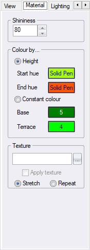
Shininess |
Enter the value of the reflectance of the colours in the view. |
|
Colour by… |
|
|
Height or Constant colour |
Select either the Height option to display the view coloured by heights; or the Constant colour option to display the view in solid colours. |
|
Start Hue and End Hue buttons |
Click to set the start and end hues of the range of colours that will be applied to the site when the Height option is selected. |
|
Base and Terrace buttons |
Click to set the solid colours that will be displayed when the Constant colour option is selected. |
|
Texture |
|
|
Texture Name |
Enter the name of the texture file to be loaded. |
|
Browse button |
Click to locate a texture file. |
|
Apply texture |
Select this checkbox to have the selected texture applied to the view. |
|
Stretch |
Distort the texture to fit the view |
|
Repeat |
Copy the texture to fit the view |
|
Option
|
Description |
|
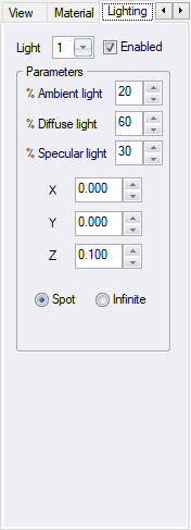
Light |
Select the light (from 1 to 8) whose parameters you want to change. |
|
Enabled |
Select this checkbox to enable the selected light. |
|
Parameters |
Enter the percentages of the types of light emitted by the selected light source. |
|
% Ambient light |
Ambient light is directionless and lights all surfaces evenly in all directions. |
|
% Diffuse light |
Diffuse light comes from a particular direction but is reflected evenly off a surface. |
|
% Specular light |
Specular light is also directional, but is reflected sharply and in a particular direction. |
|
X, Y and Z |
Enter the position of the selected light. |
|
Spot or Infinite |
Select the Spot option to have the selected light behave like a spotlight; or select the Infinite option to have the selected light behave like the sun. |
|
Option
|
Description |
|
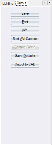
Save button |
Click to save the current view. The Bitmap Dimensions are displayed and you are asked for a filename to save to. |
|
Print button |
Click to print the current view. |
|
Info button |
Click to display information on the renderer and the version of the libraries being used. A text file called "PixelFormats.txt" is also written to the program directory and is useful in sorting out problems with the display in conjunction with the programmers. |
|
Start/Stop AVI Capture |
Click to create a new AVI file. Once capturing has started, click again to close the AVI file. |
|
Capture Frame |
Click to add the current view as a frame into the current AVI file. |
|
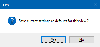
Save Defaults |
Save settings as default.
|
|
Output to CAD |
Click to have a bitmap CAD entity placed into the current project and geo-referenced to the real-world coordinates. The image will be that of a top-down view with the current lighting and material settings. The Bitmap Dimensions are displayed and you are asked for a filename to save to. |
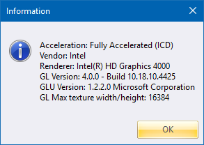
Above are examples of the type of information displayed after clicking Info. Details will change depending on the presence and use of 3D accelerator cards capable of accelerating OpenGL.
See Also 3D View, Bitmap Dimensions