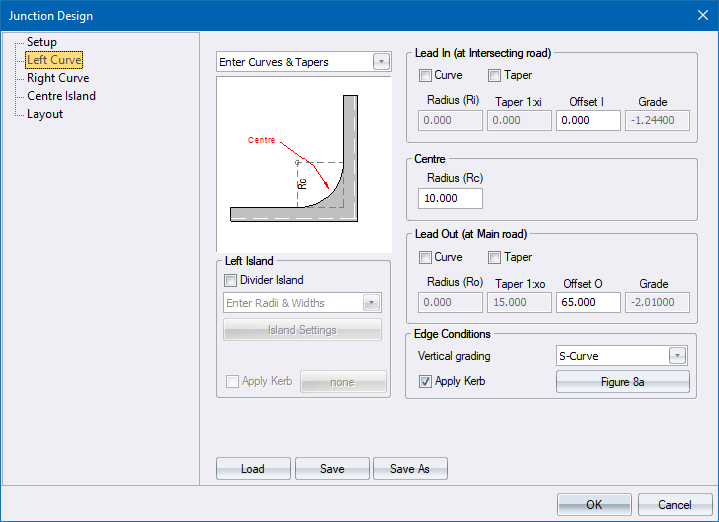
The edge of the intersection can be defined in two ways:
Enter Curves & Tapers - Specify the edge details of the intersection. Data requirements are the same for both left and right curves.
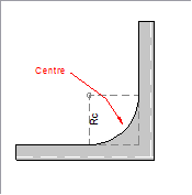
You can specify just a centre radius, or a centre radius with either a curve or taper lead in and lead out.
Option
|
Description |
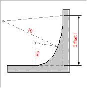
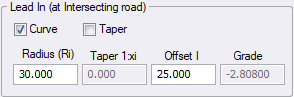
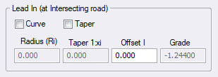
Curve |
Select this checkbox to specify a transition curve as the lead-in to the intersection curve.
The schematic layout is updated to show the radius and offset positions. |
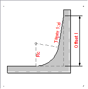
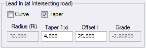
Taper |
Select this checkbox to specify a taper as the lead-in to the intersection curve.
The schematic layout is updated to show the taper and offset positions. |
Radius |
Enter the radius of the lead in curve. Only available if the Lead in Curve checkbox has been selected. |
Taper |
Enter the taper ratio as 1:x. Only available if the Lead in Taper checkbox has been selected. |
Offset |
Enter the distance from the point of edge intersection where the specified curve or taper should begin. |
Grade |
The grade of the road at this location, with the convention that at every point, facing into the intersection, negative grade is down and positive grade is up. |
Option
|
Description |
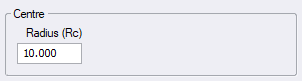
Radius |
Enter the radius of the central arc of the intersection edge. |
Option
|
Description |
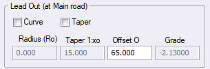
Curve |
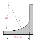
Select this checkbox to specify a transition curve as the lead-out to the intersection curve.
The schematic layout is updated to show the radius and offset positions. |
Taper |
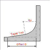
Select this checkbox to specify a taper as the lead-out to the intersection curve
The schematic layout is updated to show the taper and offset positions. |
Radius |
Enter the radius of the lead out curve. Only available if the Curve checkbox has been selected. |
Taper |
Enter the taper ratio as 1:x. Only available if the Taper checkbox has been selected. |
Offset |
Enter the distance from the point of edge intersection where the specified feature should end. |
Grade |
The grade of the road at this location, with the convention that at every point, facing into the intersection, negative grade is down and positive grade is up. |
Option
|
Description |
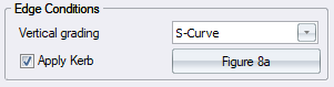
Vertical grading |
Set this option to control the vertical smoothing of bell-mouths. It can be set to one of the following:
|
Apply Kerb |
Select this checkbox to apply a kerb on this edge of the intersection. |
Select Kerb button |
Click to display the Kerb Selector and specify a kerb type. |
Option
|
Description |
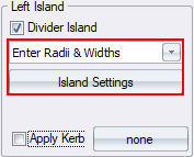
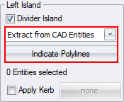
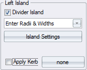
Divider Island |
If this checkbox is selected on either left or right side, the Centre Island Page will be disabled. |
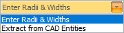
Island Type |
Select the island type from the list. There are two types:
|
Apply Kerb |
Select this checkbox to apply a kerb on this island. |
Select Kerb |
Click to display the Kerb Selector and specify a kerb type. |
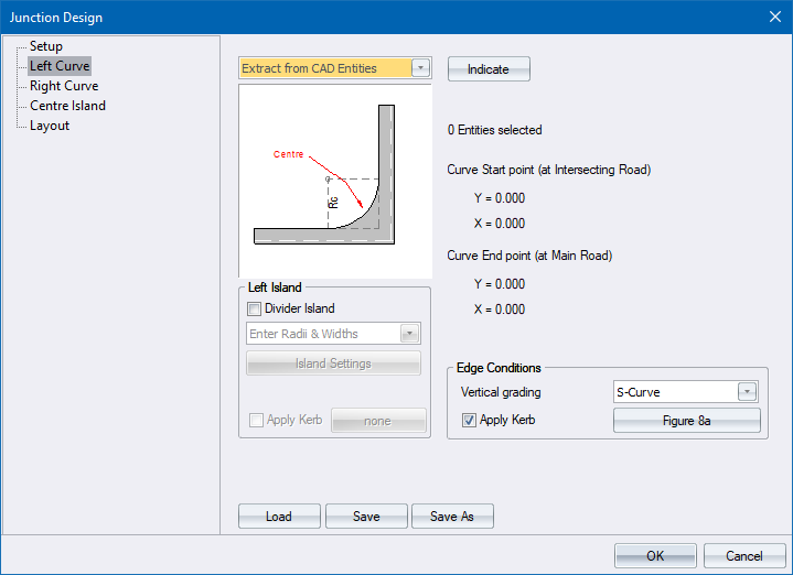
Extracting 'Left Bell Mouth' from CAD: Select Entity