 If you
want to use the extracted data in the alignment spreadsheet, run the Extract
Alignment function. In the Extract Data
from: dropdown, select the <Road
Strings model> option.
If you
want to use the extracted data in the alignment spreadsheet, run the Extract
Alignment function. In the Extract Data
from: dropdown, select the <Road
Strings model> option.Extract road centre line and edge strings from CAD and DTM.
Icon |
Command |
Shortcut Key |
Toolbar |
|
RD_REHABSTRINGS |
|
|
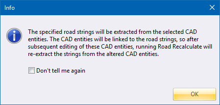
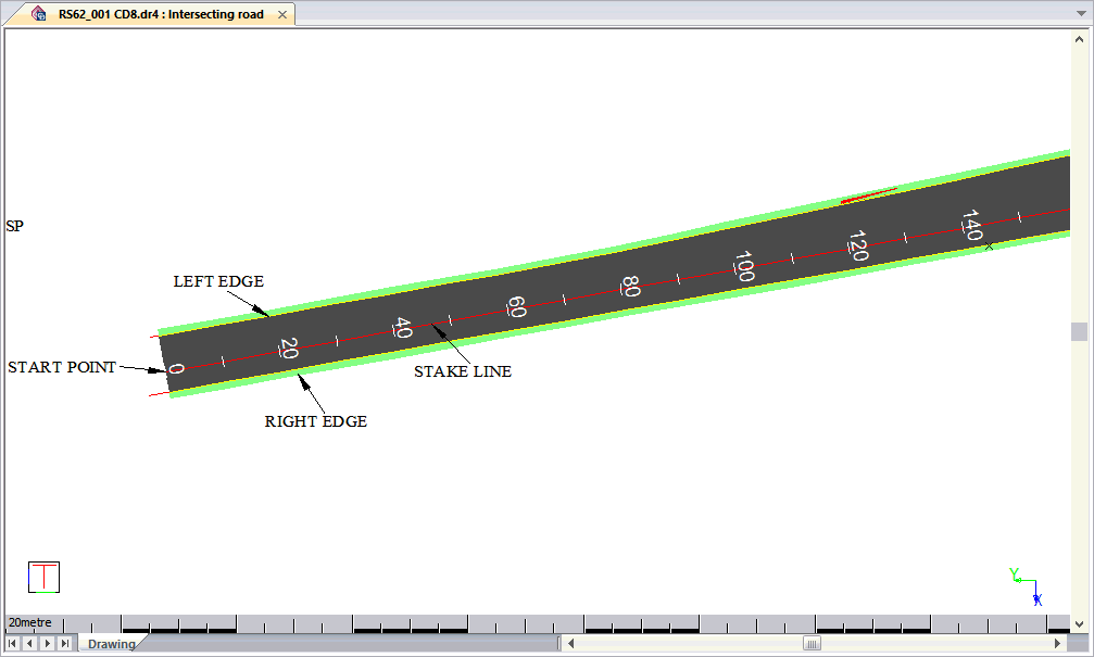
This function allows you to define the stake line, and edges of a road, from existing CAD entities. The road is created from the indicated CAD entities and the source specified for the elevations (DTM or 3D CAD entity).
If you
want to use the extracted data in the alignment spreadsheet, run the Extract
Alignment function. In the Extract Data
from: dropdown, select the <Road
Strings model> option.
Procedure
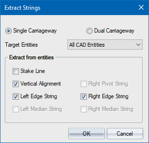
Select the carriageway type, and which entities must be extracted from the drawing. Click OK to continue.
Indicate the START point of the Stake Line
Click on the start point of the stake line. The entity must be a line or a polyline.
Indicate the END point of the Stake Line (Escape to ignore)
Click on the end point of the stake line.
Extracting 'Stake Line' from CAD: Select Entity

Should you have made a mistake in indicating the stake line entities simply right-click and select Re-define last entity or Re-define.
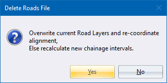
Click Yes to clear out existing road data; or No to just recalculate chainage intervals.
The program asks you to identify the CENTRE LINE (single carriageway) or L_PIVOT (dual carriageway). This determines the vertical alignment of a single carriageway, and left lane of a dual carriageway.
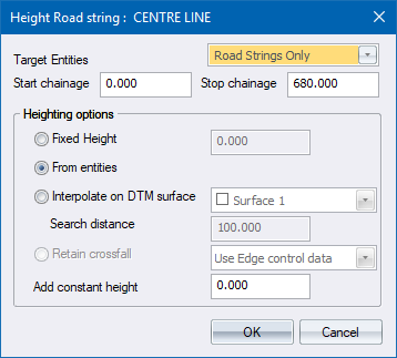
Specify where elevations (heights) for the extracted line must be found, and then click OK to continue.
The elevations are extracted and assigned to the selected road line.

Indicate the START point of the Stake Line
Indicate the END point of the Stake Line (Escape to ignore)
Extracting 'Stake Line' from another road (0 selected): Select Road string to extract from

The road string closest to the point you clicked will be selected but you can change the string you want to target here. Click Select to continue. In the same manner, you cna select multiple road strings. Right-click to display the context menu,
You can indicate multiple entities to extract your stake line from, so you will be prompted to:
Extracting 'Stake Line' from another road (1 selected): Select Road string to extract from

If you have made a mistake in indicating the stake line entities, right-click and select the Re-define last entity or Re-define option.
If the correct entities have been selected, select the Extract String option.
You are asked:

Click Yes to clear out existing road data; or No to just recalculate chainage intervals.
You are then prompted to enter the coordination interval for the Stake Line:

Specify the coordination interval and click OK to continue.
At this point, Civil Designer will automatically add two HPI points to the Horizontal Alignment - at the start and end of the extraction. If you have an existing Horizontal Alignment, you will be prompted for it to be replaced.

The Start HPI will be marked with the Extract from CAD checkbox, which means the alignment will be extracted from CAD entities between the start and end PI.
You can now continue to extract the Vertical Alignment as you specified the option in the first step.

You are prompted to:
Extracting L_PIVOT from another road (0 selected): Select Road string to extract from

Select the string you want to use and click Select.
As per steps 8 and 9 above, right-click and select the Extract String option.
At this point, Civil Designer will automatically insert two VPIs into your Vertical Alignment - at the start and end chainages specified.

The Start VPI will be marked with the Extract from CAD checkbox, which means the alignment will be extracted from CAD entities between that VPI and the next one.
Your extractions can be viewed and manipulated via the Control Centre.
