Set up the Output window parameters.
|
Icon |
Command |
|
|
OUTPUTMANAGER |
This function allows you to set up the Output Window's printing and file export capabilities. If you select to send output to the screen and the Output Window is not visible, use Window ► Toggle Output Window to display the window.
The printed output that Civil Designer produces can be:
Displayed on the screen.
Directed to your printer.
Accumulated in a disc file.
Any combination of the above is also possible. The selection option is available from all the functions and can be set or reset at any time. Therefore, it is simple to display the text for perusal and only switch it to the printer or a file when necessary.
There is also a special facility for switching on/off a warning that gives you the option to redirect your output just before any printout occurs.
When you switch output to a disc file and the specified file exists, you have the option to append the text to that which is already there, or starting again by overwriting the existing files.
A significant gain in processing speed can be achieved by turning off the screen output when it is not needed. The Output Window can be dragged and placed anywhere on the screen, or maximised if this is preferred. A rolling buffer of 1000 lines is maintained to store the screen output. A certain amount of the data that is put onto the screen and then scrolls out of sight, can be rolled back with the slide bar control.
When output is directed to a file, the file hold the simple ASCII text and can be edited or modified with any text editor. Windows Notepad and WordPad (in Text Document format) are both suitable for this purpose. When you want to generate a printout, which requires the frequent insertion of additional text or comments, it is convenient to have a copy of the text editor opened permanently alongside the Civil Designer application. This enables you to add the necessary text on the fly.
When Output is directed to a printer, make sure that the device is set up correctly. This can be done in the Printer window accessed from Start ► Settings ► Printers.
Procedure
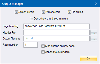
The Output Manager displays.
Make the required settings and press OK to continue.
If OK is clicked and Printer output is not checked, but it was previously checked, any output that has not yet been spooled to the printer will be sent and the current document ended.
If Printer output is now checked, and it was not previously checked, you will be asked to select the printer to which output should be directed and a new document will be started.
If OK is clicked and File output is not checked, but it was previously checked, the specified file is closed.
If File output is now checked, and it was not previously checked, the specified file is opened and will overwrite an existing file of the same name if the Append to existing file option is not checked.
A company-wide header for calculations printouts can be specified by selecting a TXT file in the Output Manager. This can typically be used for verification information required for ISO certification.
Specify a *.TXT file containing the header for printouts in the Header File field. The header will be printed just below the page header on the first page of the print. If this field is empty, no header will be printed, and the Output Manager creates a print as in previous versions of Civil Designer.
If you want the Project title to appear in the heading, add the string “{PROJNAME}” to the header text. For example, if the contents of the header file is:
Project: {PROJNAME}
Designed by: _________________________
Date: _________________________
Checked by: _________________________
Date: _________________________
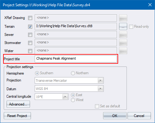
The project title can be specified in the Project Settings.
This results in the following header for all printouts.
Page 1
Knowledge Base cc 17/11/2010
=================
Project: Chapmans Peak Alignment Nov 2010
Designed by: _________________________
Date: _________________________
Checked by: _________________________
Date: _________________________
Horizontal Curve Data
=====================
Start 0.000 9093.863 3296895.705
Elements of curve No. 1 (PI1 ) Radius 100.000
=========================
In Out
== ===
Back straight 187 55 17 Transitions 25.415 25.415
Front straight 253 26 08 Tangents 77.214 77.214
Intersect angle 65 30 52 Trans. Shift 0.269 0.269
Curve direction RIGHT Arc length 88.929
Chainage Y X
======== ========= =========
PI1 9062.226 3296668.331
CC1 8971.805 3296746.046
BTC1 152.351 9072.867 3296744.808
BC1 177.766 9068.305 3296719.824
EC1 266.695 9012.231 3296654.582
ETC1 292.110 8988.217 3296646.318
Elements of curve No. 2 (PI2 ) Radius 100.000
=========================
In Out
== ===
Back straight 253 26 08 Transitions 23.100 23.100
Front straight 211 10 22 Tangents 50.281 50.281
Intersect angle 42 15 46 Trans. Shift 0.222 0.222
Curve direction LEFT Arc length 50.663
Chainage Y X
======== ========= =========
PI2 8914.311 3296624.335
CC2 8980.012 3296539.316
BTC2 318.935 8962.505 3296638.670
BC2 342.035 8940.646 3296631.242
EC2 392.698 8900.986 3296600.593
ETC2 415.798 8888.285 3296581.315
Elements of curve No. 3 (PI3 ) Radius 150.000
=========================
In Out
== ===
Back straight 211 10 22 Transitions 15.911 15.911
Front straight 235 05 00 Tangents 39.731 39.731
Intersect angle 23 54 38 Trans. Shift 0.070 0.070
Curve direction RIGHT Arc length 46.687
Chainage Y X
======== ========= =========
PI3 8831.251 3296487.040
CC3 8719.297 3296591.907
BTC3 486.252 8851.816 3296521.034
BC3 502.163 8843.342 3296507.570
EC3 548.850 8811.554 3296473.634
ETC3 564.761 8798.672 3296464.298
Elements of curve No. 4 (PI4 ) Radius 90.000
=========================
In Out
== ===
Back straight 235 05 00 Transitions 21.797 21.797
Front straight 315 15 09 Tangents 86.824 86.824
Intersect angle 80 10 08 Trans. Shift 0.220 0.220
Curve direction RIGHT Arc length 104.132
Chainage Y X
======== ========= =========
PI4 8686.180 3296385.775
CC4 8696.802 3296503.215
BTC4 615.125 8757.374 3296435.471
BC4 636.922 8739.024 3296423.734
EC4 741.054 8641.004 3296432.599
ETC4 762.851 8625.058 3296447.438
End 858.663 8557.608 3296515.485
See Also Spool Output