Home > Ground Design Difference Grid
Calculate a grid and height difference between two surfaces.
|
Icon |
Command |
Shortcut Key |
Toolbar |
|
|
TerrainGridDiff |
|
|
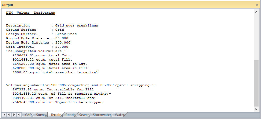
This function allows you to grid, and obtains the difference between, a "design" surface and "ground" surface.
General details are the same as those described for the Ground/Design Surface DTM. Volume details are the same as those described in the Ground/Design Surface option.
In this function, the grid points are generated only in areas where there is both ground and design data.
The grid elevations that are retained are the differences in elevation between the two surfaces.
This type of grid model is extremely useful in showing depths of cut and fill. These contours are widely used to check designs, control site earthworks and obtain "as built" data. Due to their flexibility, these isopachyte contours largely replace the traditional mass haul diagram for planning and executing bulk earthworks and dredging.
You should read the general discussion on DTM Volumes.
Procedure
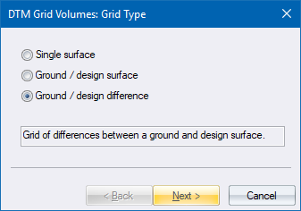
Select the Ground/design difference and click Next.
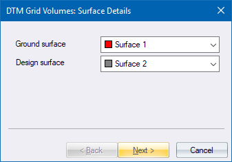
Select the relevant surfaces and click Next to continue.
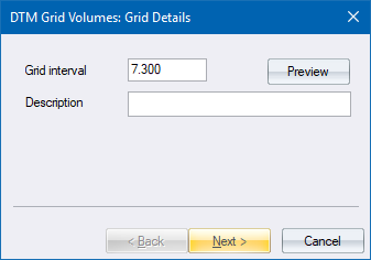
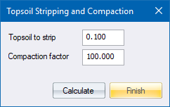
Fill in the relevant data and click Next to continue.
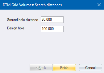
Fill in the relevant data and click Finish to continue.