Icon
Command
Shortcut Key
Toolbar
![]()
TK_MECHSPRINGS
Mechanical
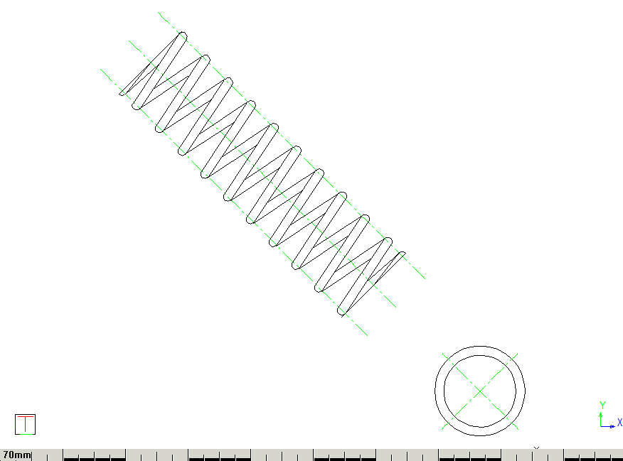
Draw springs.
|
Icon |
Command |
Shortcut Key |
Toolbar |
|
|
TK_MECHSPRINGS |
|
Mechanical |
This function allows you to draw a predefined spring, or specify and create a new spring definition.
The Mechanical Setup option defines the default line styles and pens to use.
 Make sure that the drawing units are set to "mm" (millimetres) before using the mechanical toolkit functions.
Procedure
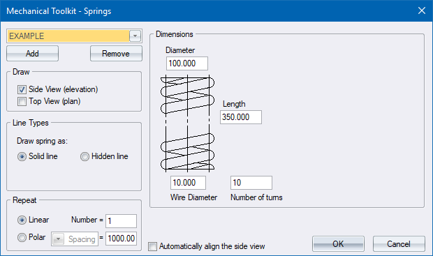
Select a predefined spring from the drop-down list, or fill in the relevant information, and then click OK.
You can add your own spring definitions by clicking Add, and then entering the relevant data. The spring definition is saved when you click OK, or select another spring definition from the list.
If you modify an existing spring definition, you are asked to save it. Select No to avoid changing the original spring definition.
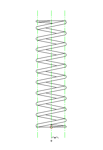
Indicate the position of the Spring side view
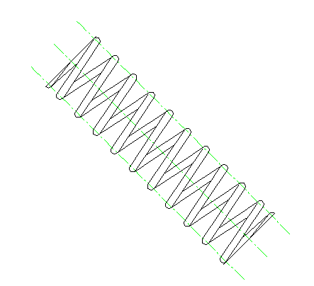
Rotate Fastner


Type in the required angle and press [Enter] or click Enter  .
.
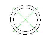
Indicate Spring centre for plan view
Cursor hold is active at this point, which allows you to specify a position for the plan view of the spring, that is aligned with the axis of the spring side view. Indicate a centre point for the plan view.
Enter a point on the Spring plan view centreline for rotation
The repeat function is used to draw multiple equidistant copies of the spring.

To draw multiple copies of the spring in a straight line:
Select the Linear option.
Enter the number of springs you want to draw.
Now enter the distance between the spring centres.
To draw multiple copies of the spring in a circular arrangement:
Select the Polar option.
Enter the number of springs you want to draw.
Select either the Spacing or PCD option from the list box.
If you select Spacing enter the distance between the spring centres.
If you select PCD enter the PCD of the circle on whose circumference the springs will be arranged.
The side view is not drawn if you select the Polar repeat option.