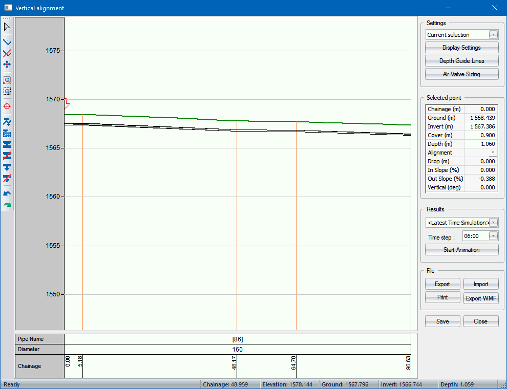
Home > Water Mode > Tools > Vertical Alignment
Display vertical alignment.
|
Icon |
Command |
Shortcut Key |
Toolbar |
|
|
WATERVERTALIGN |
|
|
This function allows you to display the vertical alignment of one or more selected pipes.
Procedure
Before using this function you need to select one or more pipes. The selected pipes should comprise a string of interconnected pipes.

The vertical bar on the right-hand side of the window contains checkboxes for items that will be displayed, either on the drawing (Hydraulic Grade Line) or in the Legend Bar. Certain options, presenting results (Flow rate, Head, Pressure and Hydraulic Grade Line), are active only in the case that Hydraulic Analysis was previously performed and that there are valid results in memory.
The Legend Bar at the bottom of the window displays a textual presentation of the longitudinal section. The scroll bar next to the legend allows vertical scrolling if the height of the legend exceeds the available space. The horizontal scroll bar is shared by the textual and graphical part of the longitudinal section.
|
Icon
|
Description
|
|
|
Select the chainage to edit. |
|
|
Insert an additional vertical alignment point in the pipe long section i.e a vertical bend in the pipe.
Click to insert a bend at the cursor position. Chainage and elevation of the cursor position are displayed at the Status Bar. |
|
|
Delete a vertical alignment point from the pipe long section.
Click near the bend to remove it. |
|
|
Move an alignment point. Click to select a bend and then click again to place it at a new position. Note that strictly vertical bends, indicated by orange vertical lines, can be moved freely in both horizontal and vertical direction; while alignment points that are both horizontal and vertical, indicated by blue lines, can be moved only in vertical direction. |
|
|
Zoom in to a defined window. |
|
|
Zoom to the extents of the long section. |
|
|
Mark the selected point on the plan. The Annotation properties window displays. |
|
|
Automatically insert air and scour valves. Displays the settings first and then inserts valves if necessary. |
|
|
Edit air and scour valves. Displays a table of air and scour valves. |
|
|
Add air valve. |
|
|
Delete air valve. |
|
|
Add scour valve. |
|
|
Delete scour valve. |
|
|
Undo. |
|
|
Redo. |
Zoom Window, Zoom In, Zoom Out and Zoom Extents work in the usual way.
|
Option
|
Description |
|
Display Settings |
Display the Settings window, which allows you to specify which data must be displayed. |
|
Depth Guide Lines |
Display the Depth Guide Lines window, which allows you to set and activate the depth guide lines. |
|
Selected point |
Display data for the selected point. You can change the invert, cover and/or depth by typing in appropriate values.
|
|
Results |
Select the results from the list, as well as the time step for time simulation. Click Start Animation to replay the hydraulic grade line for each of the time steps in the time simulation. |
|
Export |
Export the long section chainage-invert level data in CSV format. See the file format below. |
|
Import |
Import long section data from an external file in chainage-invert level format. The data format must be: Chainage, Invert, 0, 1562.410 20,1561.000 40,1562.000 88.121,1563.714 |
|
|
Print the long section. |
|
Export WMF |
Output the long section as a WMF (Windows MetaFile). |