Specify which symbols must be plotted on the cross-section, at the position(s) where the cross-section crosses lines or polylines in the CAD layers. This can be used to display fences, street lights and other items on the cross-section, where CAD lines in specified layers intersect with the cross-section.
|
Option
|
Description |
|
Table |
|
|
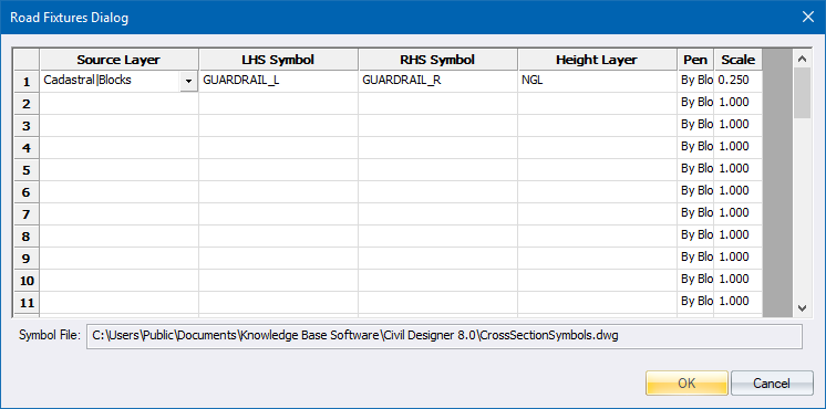
Source Layer |
Specify the CAD layer to use to determine the position of the road fixture. Where the cross-section crosses a line or polyline in the specified layer, the selected symbol will be displayed on the cross-section. |
|
LHS Symbol |
Specify which symbol must be displayed on the left-hand side intersection between the cross-section and the line/polyline in the CAD layer. |
|
RHS Symbol |
Specify which symbol must be displayed on the right-hand side intersection between the cross-section and the line/polyline in the CAD layer. |
|
Height Layer |
Specify which road cross-section layer must be used to determine the height of the reference point of the symbol. For instance, if you want to display a fence on the road reserve, it would make sense to use the natural ground layer. If, on the other hand, you want to display a guard rail on the road then you would use the final design layer. |
|
Pen |
Specify which pen to plot the symbol with. |
|
Scale |
Specify the scale of the symbol. |
|
Symbol File: |
This displays the name of the cross-section symbol file. You can edit the existing symbols or add additional symbols to this file. |