Home > Mechanical Pins/Dowels Dialog
Select a pin or dowel to be drawn.
|
Option
|
Description |
|
Pin list |
Select the active pin definition (the one you want drawn) from this list. |
|
Pin type |
Select the type of pin to be drawn. |
|
Add |
Click to add a new pin definition. |
|
Remove |
Click to delete the active pin definition. Be aware that there is no undo if you delete a pin definition by accident. |
|
Draw |
|
|
Side view |
Select this checkbox to draw a side view (elevation) of the pin. |
|
Top view |
Select this checkbox to draw a top view (plan) of the pin. |
|
Line Types |
|
|
Draw head as: Solid line/Hidden line |
Select the style in which to draw the head of the pin. Refer to the Mechanical Setup for details on styles. |
|
Draw shaft as: Solid line/Hidden line |
Select the style in which to draw the shaft of the pin. Refer to the Mechanical Setup for details on styles. |
|
Repeat |
|
|
Linear |
Select this option to linearly repeat the active pin definition after the initial pin has been drawn. |
|
Polar |
Select this option to radially repeat (drawn in a circular arrangement) the active pin definition after the initial pin has been drawn. Only works for the Top View option. |
|
Number |
Specify how many times the pin must be repeated. |
|
Distance |
Specify the distance in drawing units between repeated pins. If Polar repeat has been selected, you can specify distance as spacing (the distance between pin centre points) or as PCD (the pin is repeated along a circle with the specified diameter). |
|
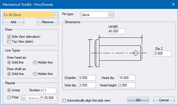
Dimensions |
Enter the relevant dimensions (in drawing units) to be used when drawing the pin. |
|
Automatically align the side view |
Select this checkbox to have the Side View, if generated, aligned with the Top View automatically. |