Icon
Command
Shortcut Key
Toolbar
![]()
MULTILINE
Drawing
Home > CAD Mode > Draw > Multiline
Draw a "Multiline" entity consisting of multiple parallel polylines at different offsets.
Icon |
Command |
Shortcut Key |
Toolbar |
|
MULTILINE |
|
Drawing |
This function allows you to draw a multiline entity consisting of multiple parallel polylines with specified offsets, by indicating the positions of the multiline vertices.
The offsets, colours, linestyles and lineweights of the parallel lines are defined by the current mulitline style.
The process of drawing is the same as for lightweight polyline, except you do not have the arc option.
 You can change the current multiline style or create new style in the
Multiline Styles
dialog.
You can change the current multiline style or create new style in the
Multiline Styles
dialog.
The appearance
of a multiline is tied to its Multiline Style. If you change a Multiline
Style, all multilines in the drawing which reference that style will reflect
the change.
Procedure

If you have created your own multiline styles, you can select them in the Style dropdown list in the Multiline bar.
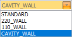
For the purposes of this example, the multiline style used has two parallel lines with offsets of "20" and "-20".
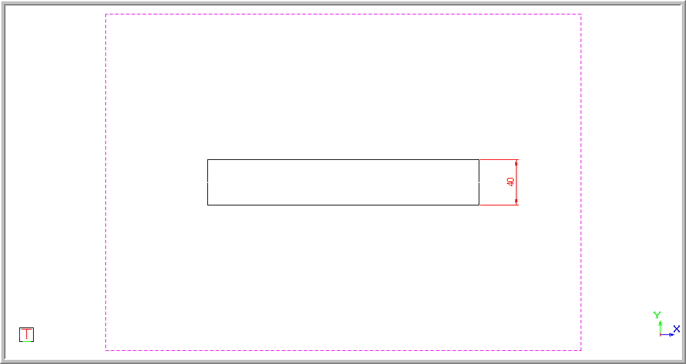
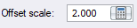
The Offset scale input in the Multiline bar scales the current multiline. The diagram below shows the example multiline style drawn with a scale of "1".

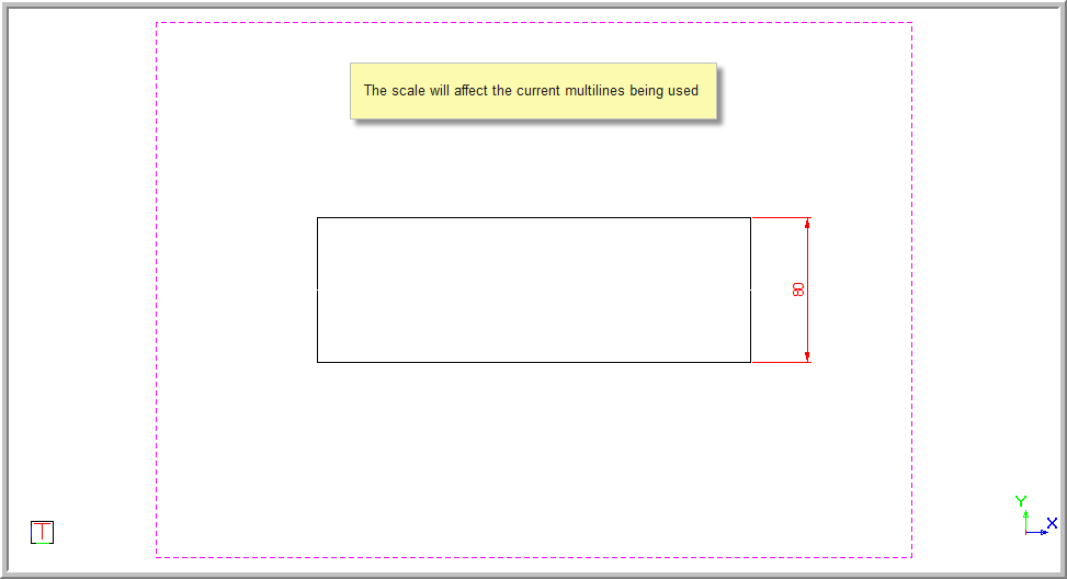
The distance offset is doubled when the scale is "2".
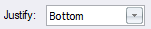
You can also specify a Justify option in the Multiline bar.
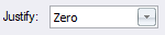
A Zero justification has the parallel elements evenly spaced from the indicated points.
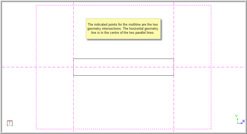
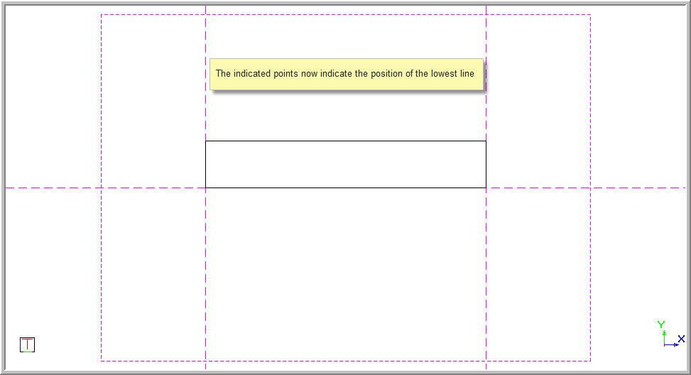
A Top justification has the indicated points being the upper most multiline.
A Bottom justification means the lowest multiline.
Once you have selected your multiline style, click in the drawing to indicate the start point.
You are prompted to:

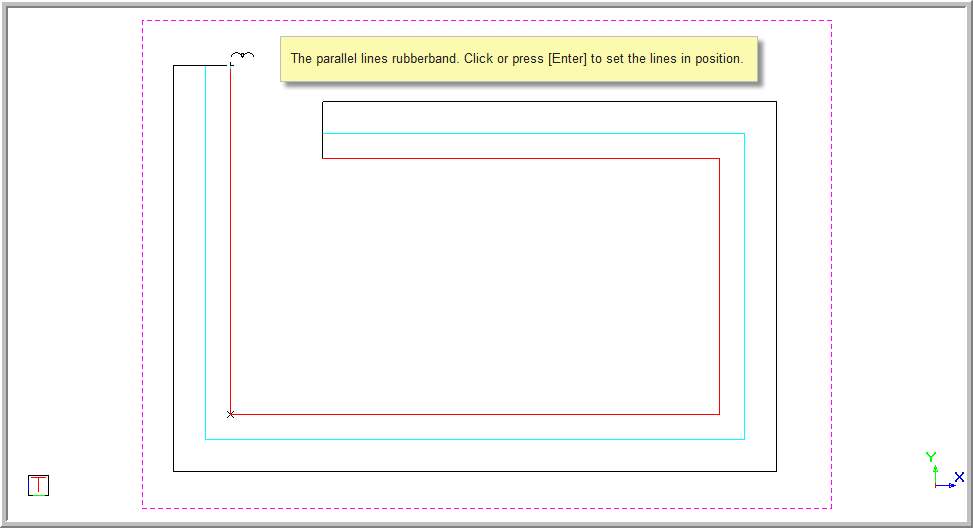
A line rubber bands as you move the mouse cursor.
Click in the drawing to indicate the next points of the multiline.
You can also use the "Radius" input in the Multiline bar to create radiused corners (fillets) in the multiline as you draw it.
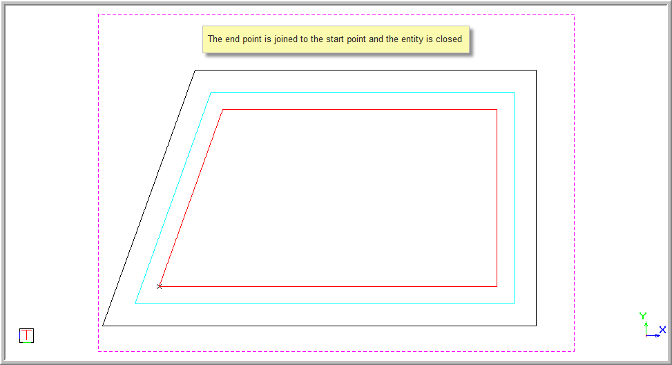
Once you have completed drawing the multiline, right-click the drawing area to open the popup context menu.
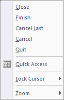
Select Close to join the end of the multiline to the start point.
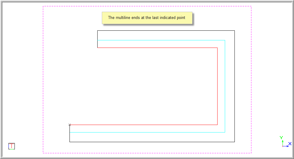
Select Finish to end the multiline at the last indicated point.
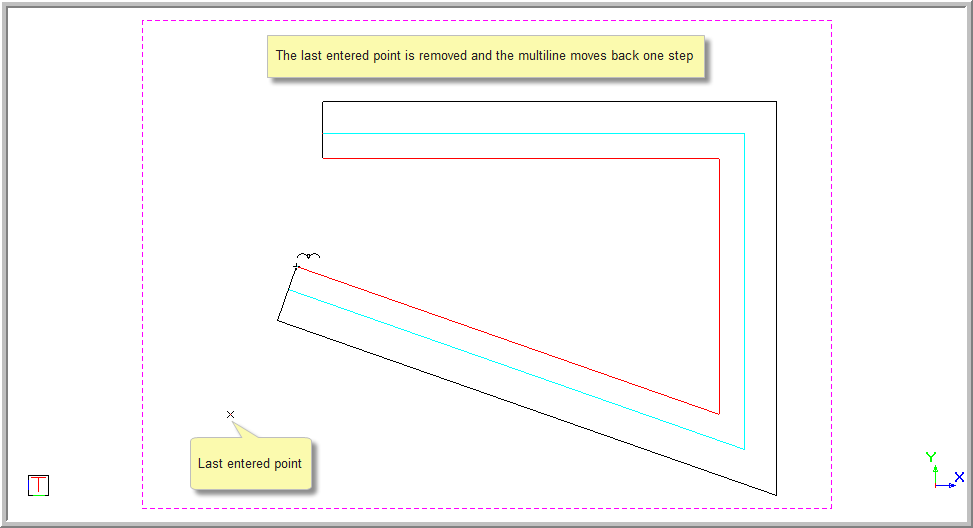
Select Cancel Last to remove the last indicated point. The line is joined to the last point indicated.
Select Cancel to stop drawing the current multiline and keep the multiline function open so that you can start the multiline over.
Select Quit to end the function completely.
You can also create a multiline from an existing boundary in the drawing. This may be useful if you, for example, want to convert a polygon into a multiline, or draw a circular multiline.
In the Main Menu, select Draw ► Multiline. The Multiline Bar will be displayed and you are prompted to:

Click Perimeter.
The Hatch/Perimeter bar displays, allowing you to select a method to specify the boundary.

Usually you would want to use the Autotracking option in the Perimeter bar, however you may also define the multiline boundary using one of the other options in the Perimeter bar (Circle, Rectangle, Polygon, By Entities, By Intersections).
Choose a perimeter method in the Perimeter bar and then follow the prompts in the CAD bar to finish specifying the perimeter for the multiline.
A multiline is generated from the perimeter you specified.