Database Linking Example
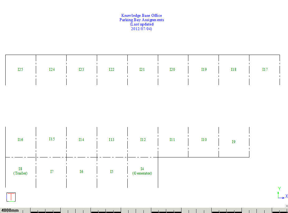
In this example we have a plan drawing of our parking bay layout. We want to associate information about staff members, which is contained in a database table, with individual bays in the parking bay plan. We also want to display the relevant info about the staff members as a label in each parking bay.
The drawing below shows an “empty” office parking layout with no staff member information linked to any of the parking bays.
Create a Data Connection
-
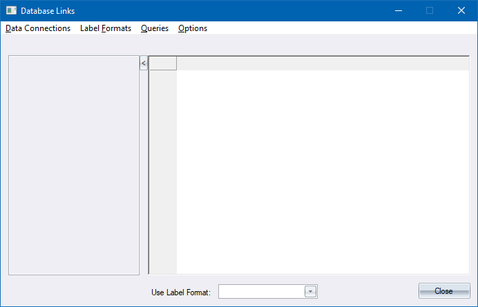
Select the Database Linking menu option to display the Database Links window.
-
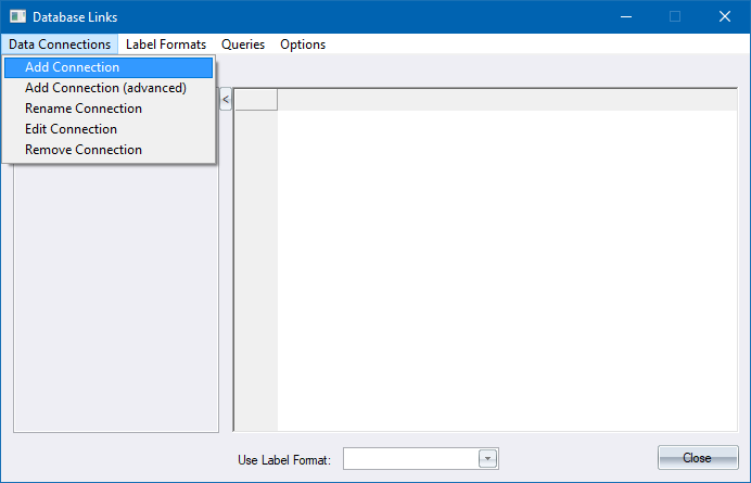
The first step is to create a data connection to an existing MS Access database. Select the Add Connection option from the menu.
-
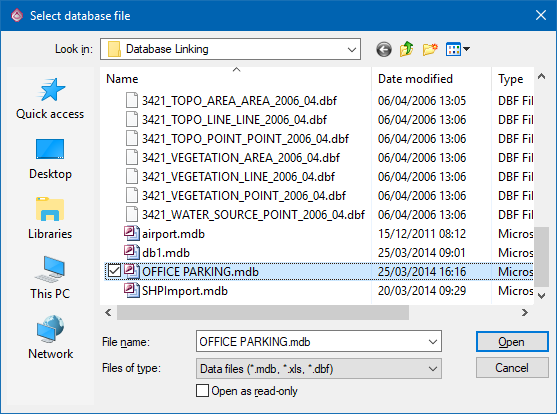
Select the existing database file called "Office Parking.mdb" and click Open.
- Enter a name for this data connection.
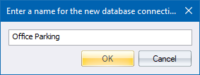
- Click OK to accept the default name for this connection. The Office Parking connection is shown in the connection tree on the left side of the Database Links window.
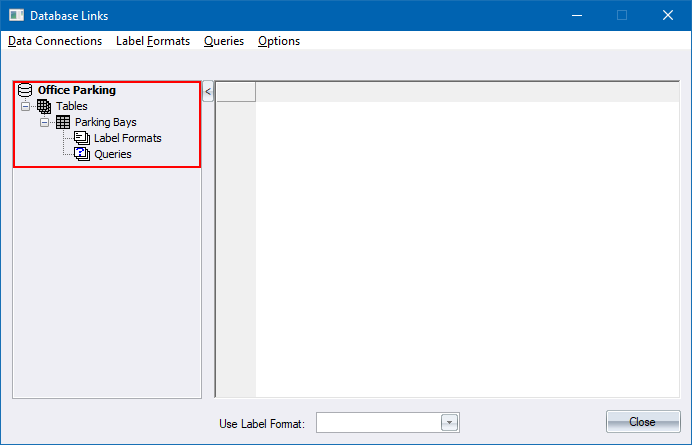
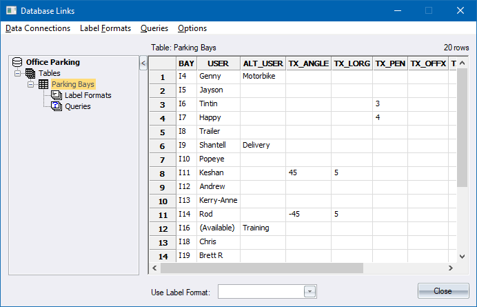
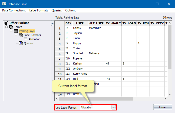
- Select Parking Bays in the Tables item in the tree to display the information in the Parking Bays table.
Define a Label Format
We are going to use the Link with Labels function to link specific rows in the table to individual bays in the drawing. Because we are creating labels, we first need to define an appropriate label format for the labels.
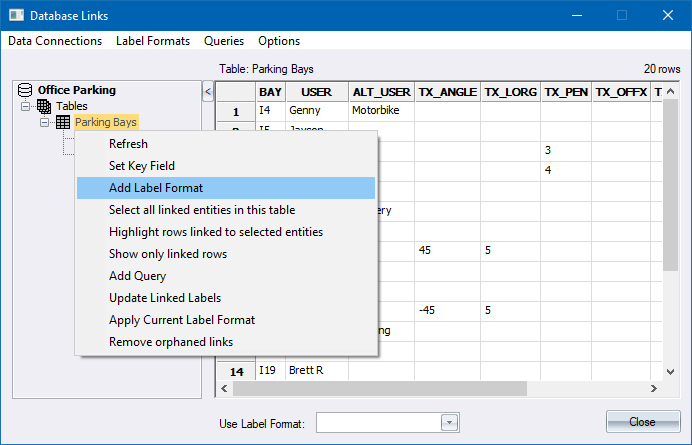
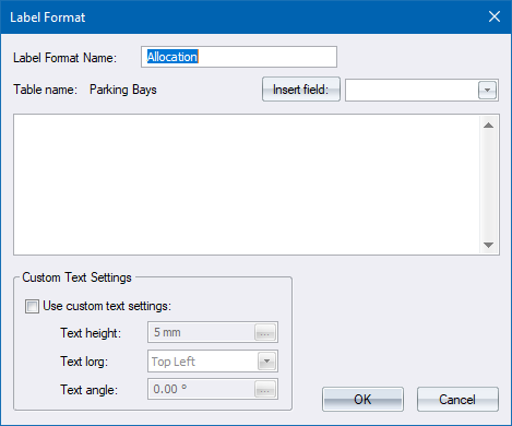
- Right-click on the Parking Bays node in the connection tree and select the Add Label Format option from the popup menu.
-
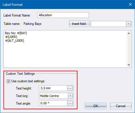
The Label Format settings display. Specify "Allocation" as the label format name.
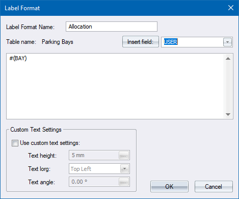
- Insert the fields “BAY”, “USER” and “ALT_USER” into the label format window using the field listbox.
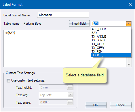
- Click Insert field: after selecting each field.
- Separate the field specifications by pressing [Enter]. Your final label format should look like this:
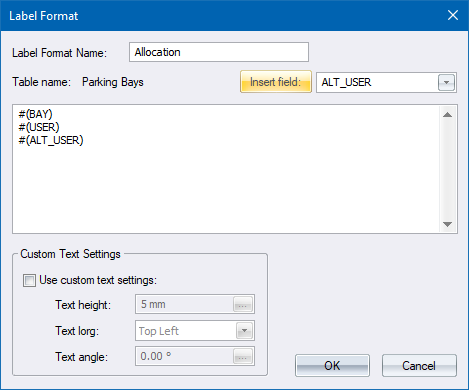
- You can also include additional text in the label format as shown below.
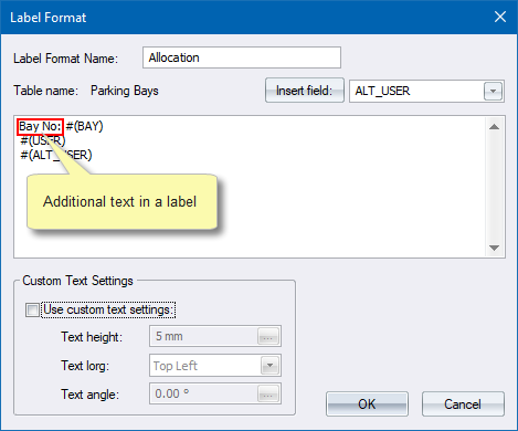
- Click OK to accept the label format. It will become the current label format when we create link labels.
- Since the label text will be created using the current Text Style settings, check that the current Text Style is set to “DEFAULT” and that it has a height of approximately 2.5mm on paper.
Linking the Database to a Drawing Entity
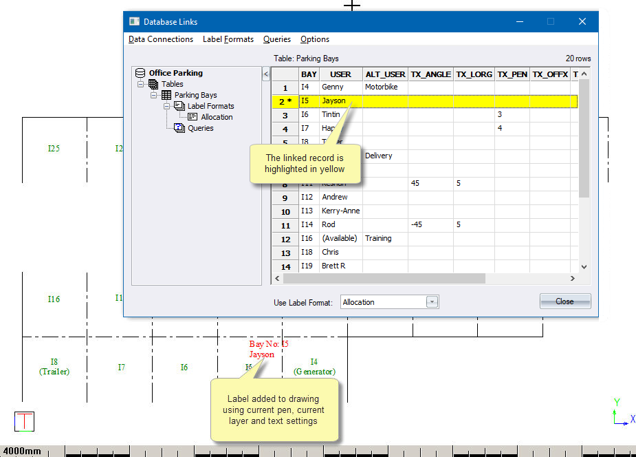
- Right-click on the row numbered “2” (data for BAY I5), and select Link with Label option.
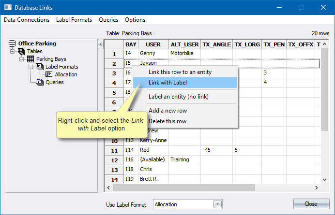
- You are prompted to:
Indicate entity to link (BAY = I5)
- In the drawing, click on bay number “I5”.
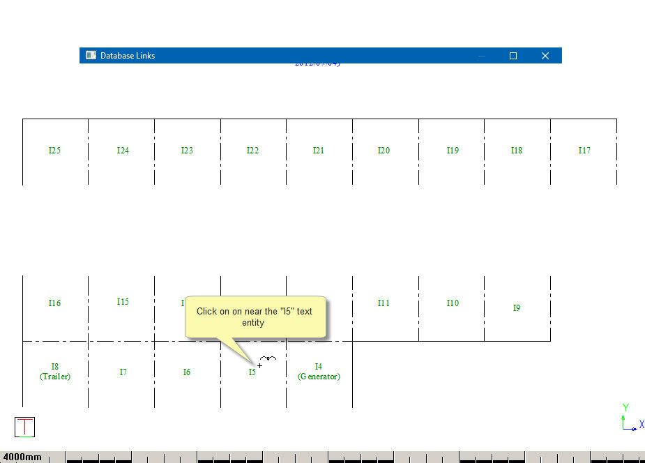
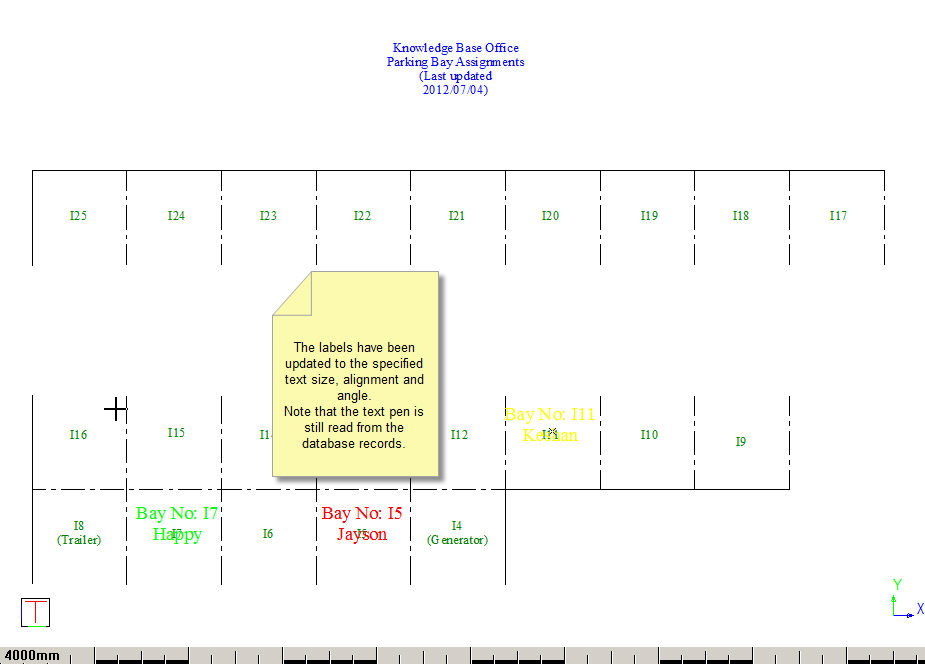
- The label “Bay No: I5 / Jayson” displays in the drawing and the relevant row in the data grid in the Database Links is highlighted in yellow.
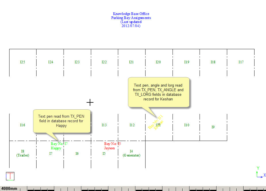
- Continue to use the Link with Label function to link the data for Keshan (I11) and Happy (I7) to their respective parking bays. Notice how the colour of the labels is taken from drawings current pen, unless there is a “TX_PEN” column in the database table with a valid pen number. Similarly, the lorg (alignment) of the label defaults to bottom-left, unless overridden by a valid lorg number in the “TX_LORG” column.
- To override the text settings used by the label, you can select the Custom text settings option in the Label Format. Right-click the Allocation label format in the connection tree and select Edit from the popup menu.
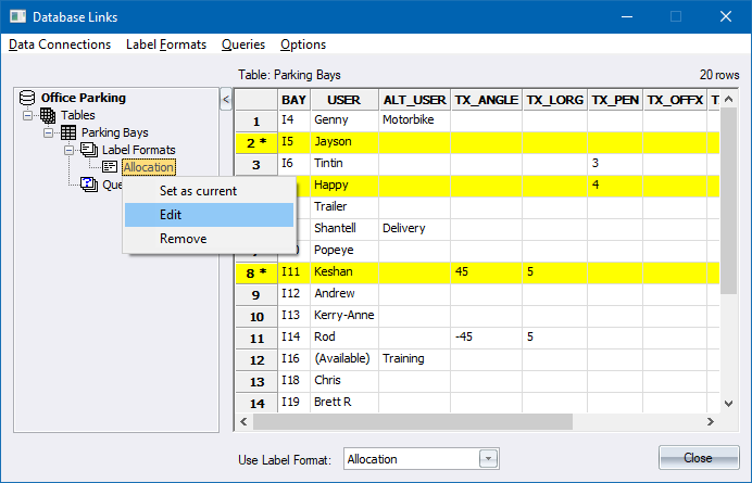
- Set up custom label format text settings as below.
-
Click OK to accept your changes to the label format.
- Right-click the Parking Bays table node in the connection tree and select the Update Linked Labels option from the popup menu.
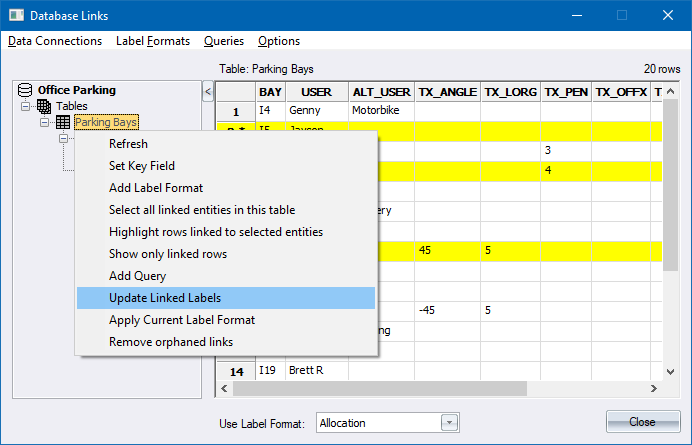
- The labels are updated and should now match your custom label format settings.
- We can now use database linking features including:
- Zoom to entity
- Select an entity from the database
- Select all the linked entities
- Show which records in the database are linked to selected drawing entities
- Show a selected drawing entity's linked database record
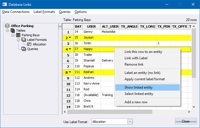
Zoom to Entity
- Select the database record that you want to locate, right-click and select the Show linked entity option to zoom to the entity linked to the relevant data row.
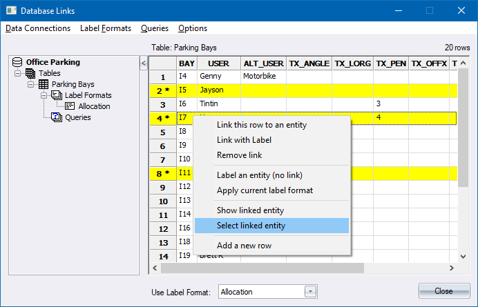
Select an Entity from the Database
- Select the database record of the entity that you want to select, right-click and use the Select linked entity option to select the entity linked to the relevant data row.
Select All the Linked Entities
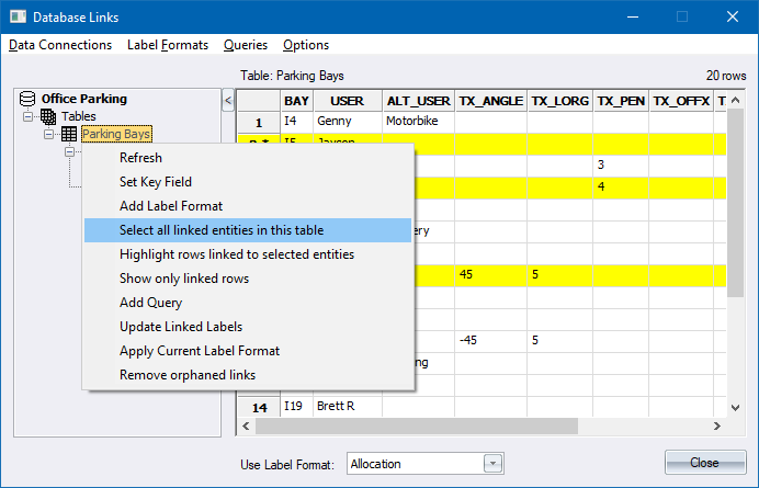
- Select the Parking Bays table in the connection list, right-click and select the Select all linked entities in this table option to make all the entities linked to data in the current table selected.
Show Which Records in the Database are Linked to Selected Drawing Entities
-
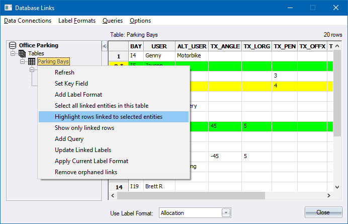
Select a number of drawing entities, including some that are linked to the database.
- Now click in the Parking Bays table in the database connection list, right-click and select the Highlight rows linked to selected entities option to show the database records of selected drawing entities in green.
Show a Selected Drawing Entity's Linked Database Record
- Select a drawing entity, right-click and select the Show Linked Data option from the popup menu.
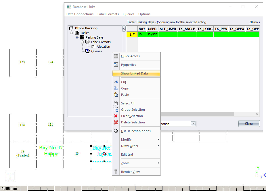
- The link data record for the selected entity is displayed in the Database Links window.