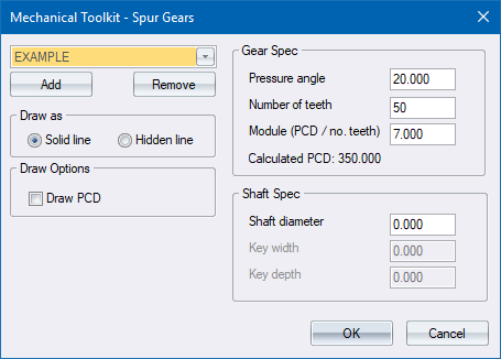
Select a spur gear to be drawn.
|
Option
|
Description |
|
Gear list |
Select the active gear definition (the one you want drawn) from this list. |
|
Add |
Click to add a new gear definition. |
|
Remove |
Click to delete the active gear definition. Be aware that there is no undo if you delete a gear definition by accident. |
|
Draw as |
|
|
Solid line/Hidden line |
Select the style in which to draw the gear. Refer to the Mechanical Setup Dialog for details on styles. |
|
Draw options |
|
|
Draw PCD |
Select this option to draw the pitch circle of the gear. |
|
Gear Spec |
|
|
Pressure angle |
Enter the pressure angle for the gear in degrees. This value is normally set to 14.5, 20 or 25 degrees. |
|
Number of teeth |
Enter the number of teeth the gear must have. Reasonable values are between 4 and 1000. |
|
Module (PCD/no. teeth) |
Enter the module of the gear. The gear PCD will be calculated and displayed. |
|
Shaft Spec |
|
|
Shaft diameter |
Enter the shaft diameter in drawing units. Enter 0 if you do not want a shaft to be drawn. |
|
Key width |
Enter the width (in drawing units) of the keyway in the gear. Enter 0 if you do not want a keyway to be drawn. |
|
Key depth |
Enter the depth (in drawing units) of the keyway in the gear. The depth is measured from the edge of the key. |
 The Draw PCD option is useful for aligning a gear and pinion.